Clutch device for washing machine

A technology for washing machines and clothes, applied in clutches, non-mechanical drive clutches, washing devices, etc., can solve problems such as increased power consumption and achieve the effect of reducing power consumption

Inactive Publication Date: 2003-01-29
LG ELECTRONICS INC
View PDF0 Cites 8 Cited by
  • Summary
  • Abstract
  • Description
  • Claims
  • Application Information

AI Technical Summary

Problems solved by technology

Therefore, power consumption increases

Method used


Image

  • Clutch device for washing machine
  • Clutch device for washing machine
  • Clutch device for washing machine

Examples


Embodiment Construction

[0053] Embodiments of a clutch device for a washing machine according to the present invention will now be described in detail with reference to the accompanying drawings.

[0054] The clutch device of the washing machine according to the invention can have several embodiments. However, preferred embodiments of the present invention will now be described.

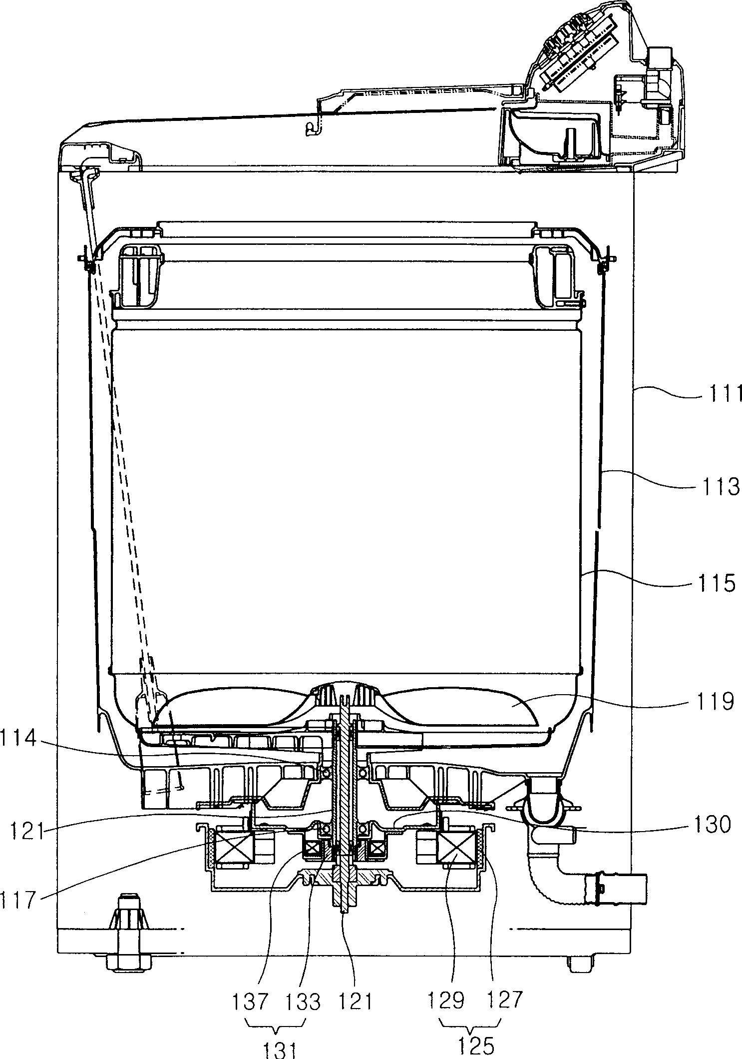
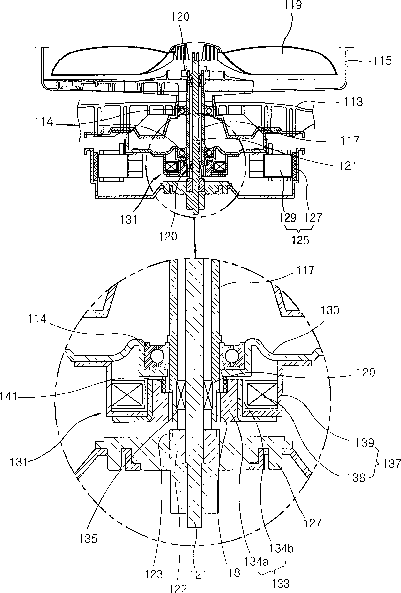
[0055] image 3 is a vertical sectional view showing a clutch device according to an embodiment of the present invention. Figure 4 yes image 3 Enlarged view of the main part shown.

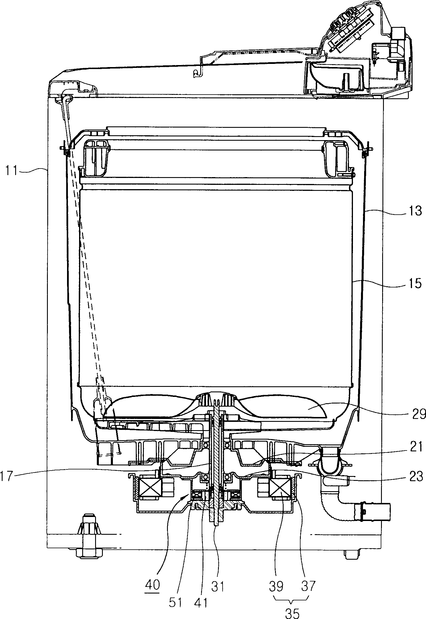
[0056] refer to image 3 , the washing machine using the clutch device according to the present invention comprises: a housing 11; a tub 13 installed in the casing 11, the tub 13 interior stores water; a rotating laundry basket 15 arranged in the tub 13 inside, the rotary laundry basket 15 is used for washing clothes; an agitator 29 arranged inside the rotating clothes basket 15 rotates relative to the rotating clothes basket 15; and a d...


PUM


Abstract

A clutch apparatus of a washing machine is provided. The clutch apparatus includes a coupling unit comprising a magnetic unit at least in one part, combined around the basket shaft, and combined with a rotor of the driving motor in a state where the coupling unit moves downward, the coupling unit for transmitting the rotary power of the driving motor to the basket shaft and a solenoid actuator comprising a solenoid coil and fixed to the lower portion of the tub, the solenoid actuator for supplying electromagnetic repulsive force between the solenoid actuator and the coupling unit so that the coupling unit is separated from the rotor of the driving motor, to thus push the coupling unit upward. The clutch apparatus is formed to have a repulsive type structure unlike a conventional attractive type clutch apparatus. Accordingly, it is possible to collision noise generated when the coupling unit rises and to reduce the amount of consumption of power for maintaining a state where the coupling member rises.

Description

technical field [0001] The present invention relates to a clutch device of a washing machine. More particularly, it relates to a clutch device of a washing machine that controls the transmission of rotational power from a driving motor to a laundry basket shaft using electromagnetic force. Background technique [0002] figure 1 is a vertical sectional view showing a washing machine having a clutch device according to the prior art. [0003] usually, figure 1 The washing machine shown comprises: a casing 111 forming an inner storage space; a tub 113 installed in the casing 111, and the tub 113 stores water inside; a rotating clothes basket 115 arranged in the tub 113, rotating the clothes basket 115 is used for washing clothes; an agitator 119 arranged inside the rotating clothes basket 115 rotates relative to the rotating clothes basket, and the agitator 119 is used to form a water flow; and a driving motor 125 formed at the bottom of the bucket 113 drives The motor 125 ...

Claims


Application Information

Patent Timeline
Patent Type & Authority Applications(China)
IPC IPC(8): D06F37/40F16D27/118
CPCD06F37/40
Inventor 金东勳安埈澔
Owner LG ELECTRONICS INC
Why Eureka
Try Eureka