Film packaged external pin pressing device

A technology of thin-film packaging and external pins, which is applied to optics, instruments, electrical components, etc., can solve problems such as time-consuming, low production line efficiency, and increased personnel training costs

Inactive Publication Date: 2003-02-05
HANNSTAR DISPLAY CORPORATION
View PDF0 Cites 2 Cited by
  • Summary
  • Abstract
  • Description
  • Claims
  • Application Information

AI Technical Summary

Problems solved by technology

[0005] In the above crimping device, since the operator must rotate the nut 160 when he wants to adjust the crimping height d, and the nut 160 is located in the middle of the crimping device 100, so the operator must start from the left side of the support plate 150. side, use a special open-end wrench to reach the nut 160, and it will be blocked by the support plate 150 and the crimping head assembly 130 during the adjustment process, so that the adjustment space is insufficient, often takes a lot of time, and the effect may not be very good, resulting in Production line efficiency underground inefficiency
Moreover, in the above-mentioned adjustment process, the skills required are relatively high. Whenever a product is replaced, it is often necessary to rely on skilled technicians to adjust and correct the crimping height d. Therefore, it takes a while when personnel change. Time to become familiar with its more difficult operating skills, resulting in increased personnel training costs

Method used


Image

  • Film packaged external pin pressing device
  • Film packaged external pin pressing device
  • Film packaged external pin pressing device

Examples


Embodiment Construction

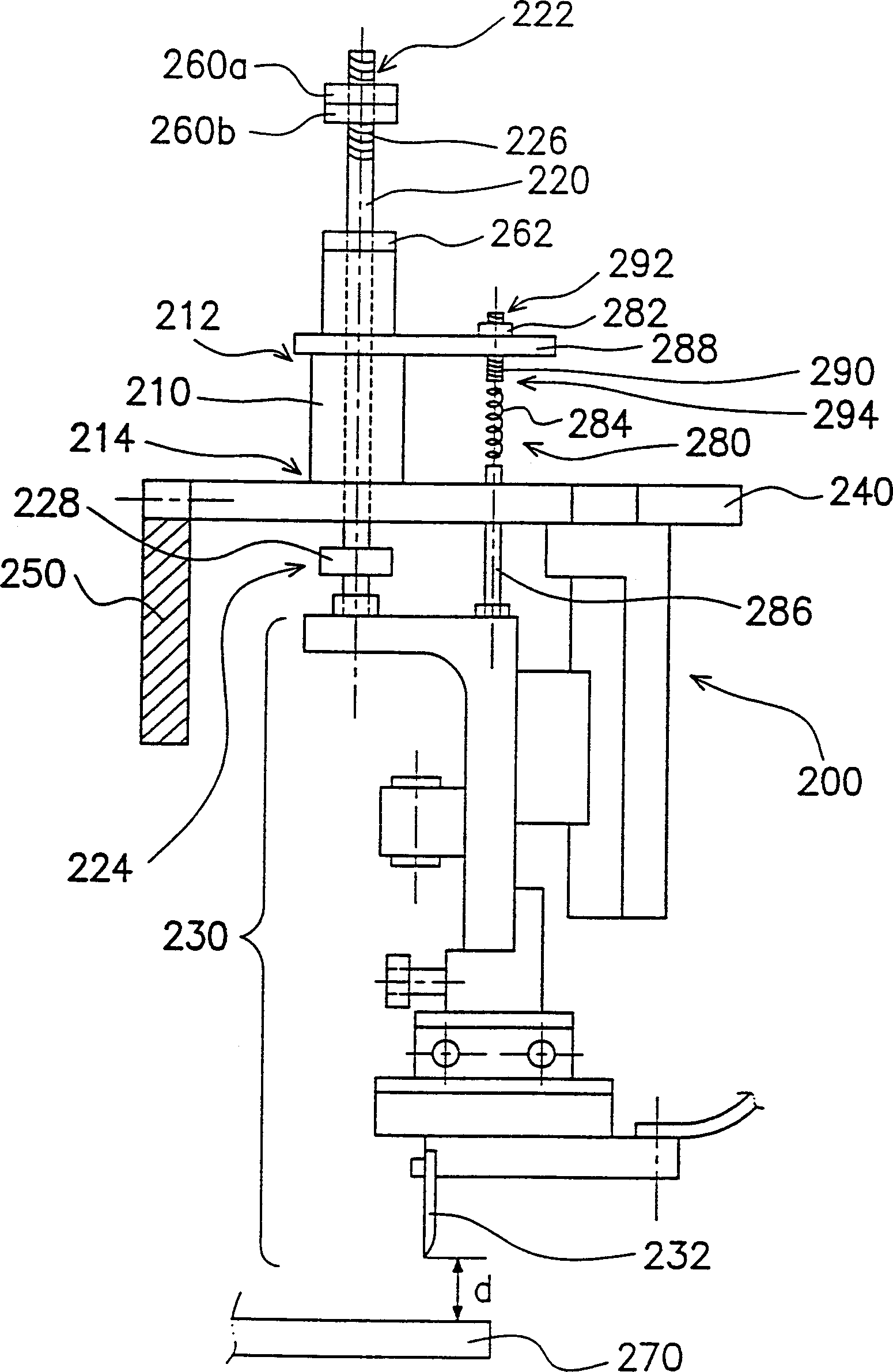
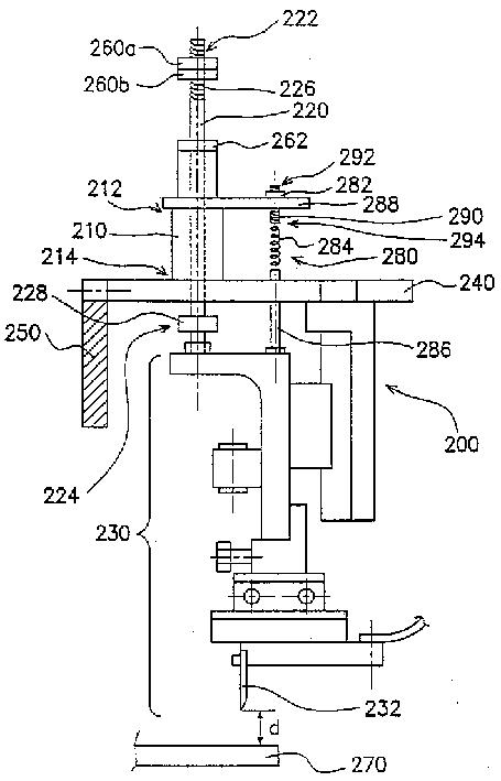
[0034] Please refer to figure 2 , the crimping device 200 includes a cylinder 210, a connecting rod 220, a crimping head assembly 230, a platform 240, and a support plate 250, wherein the platform 240 is fixed on the support plate 250, and the cylinder 210 is fixed on the platform 240 superior. The cylinder 210 has a first end 212 and a second end 214, and the connecting rod 220 runs through the inside of the cylinder 210, and the connecting rod 220 has a first end 222 and a second end 224, and the first end 222 of the connecting rod 220 extends out of the cylinder 210 The outside of the first end 212 of the connecting rod 220 is connected with an adjustment assembly, and the first end 222 of the connecting rod 220 has a threaded structure 226, and the adjustment assembly is composed of two adjustment nuts 260a, 260b, the adjustment nut 260a , 260b are bolted on the threaded structure 226 . The second end 224 of the connecting rod 220 extends out of the second end 214 of th...


PUM


Abstract

The invented device for clamping the outer pins for the film encapsulation includes at least the one cylinder, one connecting rod and the clamping head assembly. The cylinder possesses the first end and the second end. The connecting rod is throughout the cylinder. The connecting rod also possesses the first end and the second end. The first end of the rod is extended to the outside of the first end of the cylinder, and the second end of the rod is extended to the outside of the second end of the cylinder. The screw thread structure is on the first end of the rod. There is the spacer between the adjusting nut and the cylinder. The floating joint constitutes the second end of the rod. The clamping head assembly is connected to the floating joint of the rod.

Description

technical field [0001] The invention relates to a crimping device for outer pins of thin film packaging, and in particular to a crimping device for outer pins of thin film packaging that can simplify adjustment procedures. Background technique [0002] Generally speaking, the thin film packaging (Tape Carrier Package, TCP) is usually used in the electrical connection between the liquid crystal display (Liquid Crystal Display, LCD) and the driver chip. In terms of thin film packaging technology, it is to provide a thin film carrier (Tape Carrier) , carrying a plurality of inner leads and a plurality of outer leads, electrically connected to the driver chip through the inner leads, and electrically connected to the liquid crystal display through the outer leads. There are many ways to connect the external pins to the liquid crystal display, including soldering or using Anisotropic Conductive Film (ACF). Anisotropic conductive adhesive is a resin in which metal fine powder (ni...

Claims


Application Information

Patent Timeline
Patent Type & Authority Applications(China)
IPC IPC(8): G02F1/1333H01L21/60
Inventor 陈春荣
Owner HANNSTAR DISPLAY CORPORATION
Why Eureka
Try Eureka