

Small pump, cooling system and portable instrument
A technology for cooling systems and small pumps, which is applied to pumps, pump components, variable capacity pump components, etc. It can solve the problems of small discharge flow and increase the diaphragm area, and achieve the effect of large discharge flow and stable discharge flow characteristics
- Summary
- Abstract
- Description
- Claims
- Application Information
AI Technical Summary
Problems solved by technology
Method used
Image

Examples
Embodiment Construction
[0053] Hereinafter, the present invention will be described in more detail using embodiments.
[0054] (first implementation)
[0055] A first embodiment of the present invention will be described below with reference to the drawings.
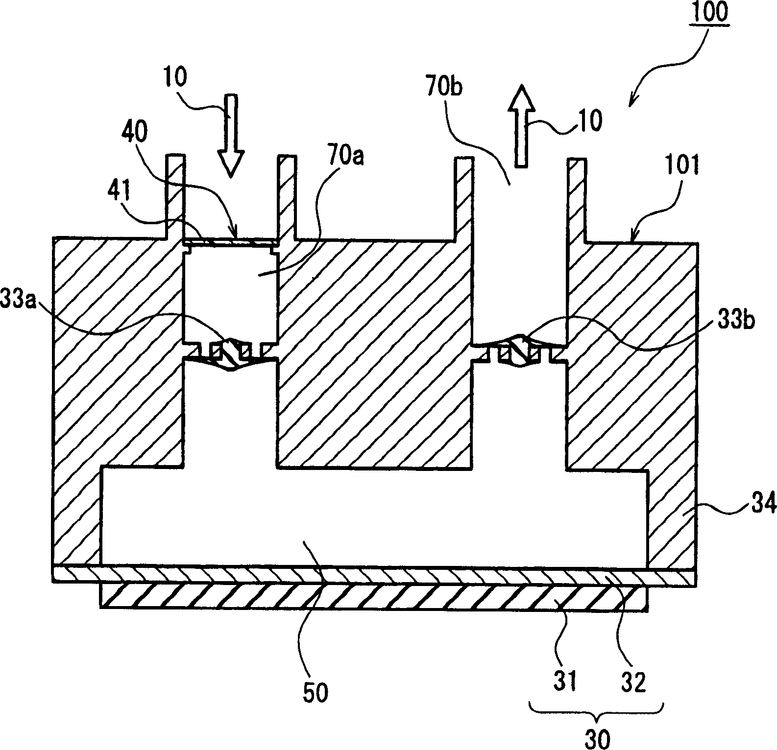
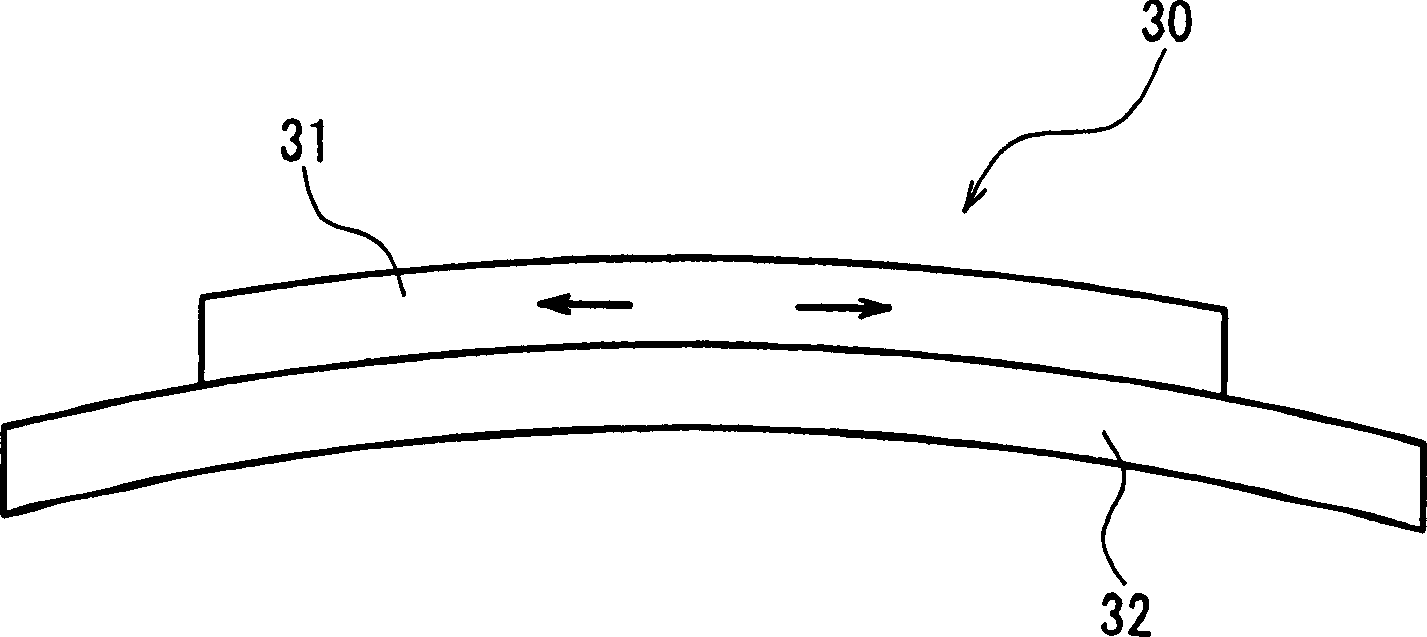
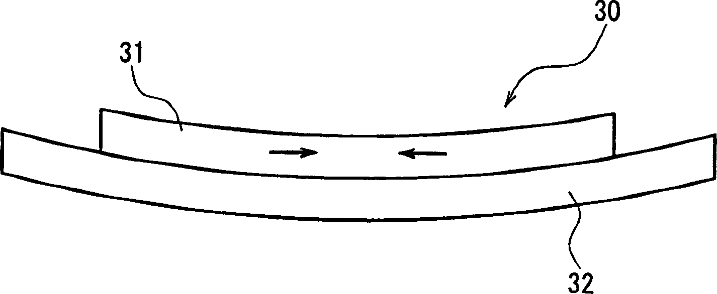
[0056] figure 1 is a schematic sectional view of the small pump 100 according to the first embodiment of the present invention. The small pump 100 basically includes a small pump unit 101 and an air bubble trap 40 . The small pump unit 101 has the following parts: the suction flow path 70a through which the fluid flows in; the discharge flow path 70b through which the liquid flows out; the pressurization chamber 50 provided between the suction flow path 70a and the discharge flow path 70b; The piezoelectric vibrating plate (movable member) 30 that changes the volume of the chamber 50; is provided on the inflow passage into the pressurization chamber 50, and prevents the liquid flowing into the pressurization chamber 50 from the suction flow ...
PUM
 Abstract
Description
Claims
Application Information