Oil mist separator

a technology of oil mist separator and separator, which is applied in mechanical equipment, dispersed particle filtration, transportation and packaging, etc., can solve the problems of filter devices that achieve only a limited degree of separation, and achieve the effects of reducing cross-sectional area, reducing flow cross-sectional area, and increasing the flow speed of carrier gas

Active Publication Date: 2017-01-10
GE JENBACHER
View PDF38 Cites 1 Cited by
  • Summary
  • Abstract
  • Description
  • Claims
  • Application Information

AI Technical Summary

Benefits of technology

[0010]It is possible in that way to avoid by-passing of the filter device by components of the carrier gas.
[0011]To increase a flow speed of the carrier gas and/or to achieve a prolonged—preferably labyrinth-like—flow path for the carrier gas through the at least one filter insert at least one guide device is provided by which the flow path can be deflected.
[0012]A guide device arranged along the flow direction provides for a reduction in the flow cross-section available to

Problems solved by technology

By virtue of the underlying separation mechanisms and the structure-governed design configuration of such a wire mesh or knitted wire mesh, however, such fi

Method used


Image

  • Oil mist separator
  • Oil mist separator
  • Oil mist separator

Examples


Embodiment Construction

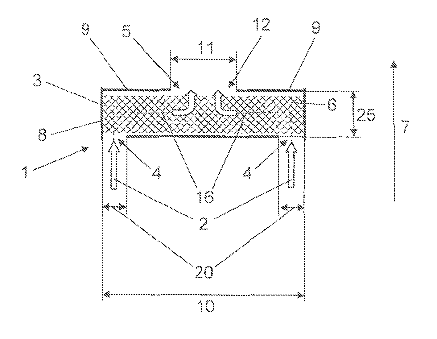
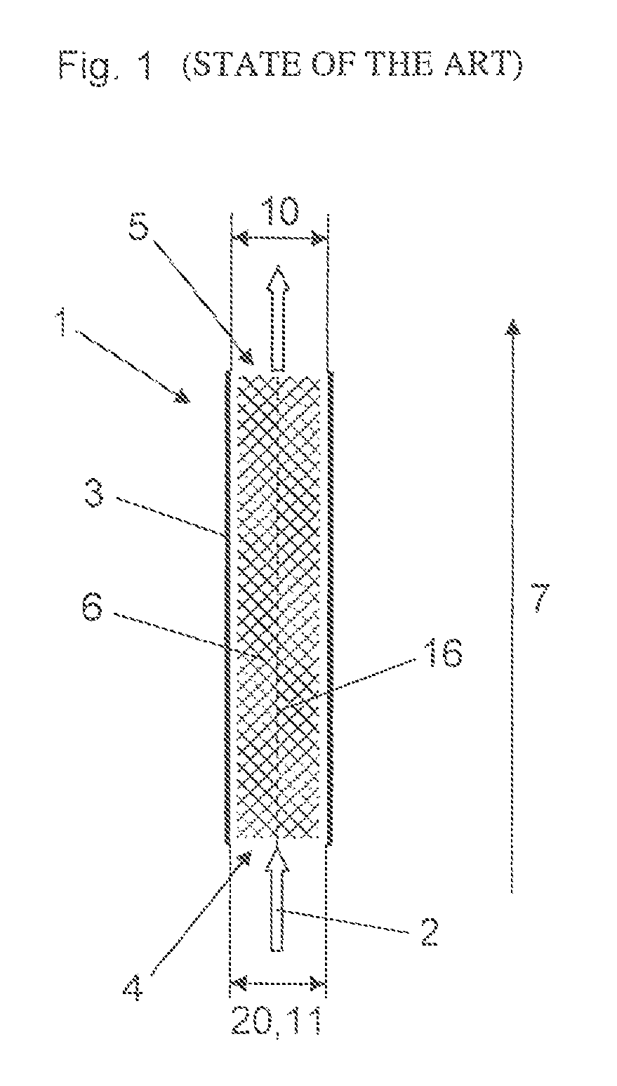
[0036]FIG. 1 is a diagrammatic sectional view of a filter device 1 according to the state of the art, including a housing 3 and a filter insert 6 arranged in the housing 3. The housing 3 of the filter device 1 has an inlet opening 4 for the introduction of a carrier gas 2 into the filter device 1 and an outlet opening 5 for discharge of the carrier gas 2 filtered by the filter insert 6 from the filter device 1. The flow of the carrier gas 2—from which liquid suspended particles like, for example, oil are to be separated off—through the filter insert 6 along a flow path 16 is indicated by a broken line. Starting from the inlet opening 4 towards the outlet opening 5, the carrier gas 2 flows through the filter device 1 along a flow direction 7. In this example, in transverse relationship with the flow direction 7, the housing 3 is of a substantially rectangular cross section so that there is a rectangular internal housing cross-section 10, transversely relative to the flow direction 7....


PUM

PropertyMeasurementUnit
Fractionaaaaaaaaaa
Fractionaaaaaaaaaa
Fractionaaaaaaaaaa

Abstract

An oil mist separator includes at least one filter device for separating off liquid suspended particles from a carrier gas. The filter device includes a housing having at least one inlet opening for introducing the carrier gas and at least one outlet opening for discharging the filtered carrier gas. Arranged in the housing is at least one filter insert through which the carrier gas can flow along a flow direction. There is also provided at least one guide device by which the flow path can be deflected. The at least one filter device can be arranged releasably in the oil mist separator, and a seal is provided preferably between a first fixing surface of the oil mist separator and a second fixing surface, to be fixed thereto, of the filter device.

Description

BACKGROUND OF THE INVENTION[0001]1. Field of the Invention[0002]The invention concerns an oil mist separator for separating off liquid suspended particles from a carrier gas, in particular, a crankcase ventilation gas of an internal combustion engine, including a housing having at least one inlet opening for introduction of the carrier gas and at least one outlet opening for discharge of the filtered carrier gas, wherein arranged in the housing is at least one filter insert through which the carrier gas can flow along a flow direction.[0003]2. Description of Related Art[0004]It is known that in operation of an internal combustion engine so-called blow-by gases are produced, which are to be discharged from a crankcase of the internal combustion engine to avoid an increase in the pressure in the crankcase and to prevent unwanted escape of blow-by gas and oil contained therein. In the closed crankcase ventilation system, that crankcase venting gas or the carrier gas which includes oil ...

Claims


Application Information

Patent Timeline
IPC IPC(8): F01M13/04B01D45/08B01D46/00
CPCF01M13/04B01D45/08B01D46/003B01D46/0023F01M2013/0433F01M2013/0438F01M2013/0461B01D46/62
Inventor WALL, GUENTHERLAUBACH, JOHANNESMADL, WOLFGANGTRENKWALDER, THOMAS
Owner GE JENBACHER
Why Eureka
Try Eureka