
Flow adjusting device and common rail system

A flow regulating device and flow amplification technology, which is applied in the direction of charging system, fuel injection device, engine components, etc., can solve the problems of small leakage flow, low opening pressure, unsuitable common rail system, etc., and achieve the goal of increasing oil leakage Effect

Inactive Publication Date: 2021-07-02
FAW JIEFANG AUTOMOTIVE CO
View PDF5 Cites 1 Cited by
  • Summary
  • Abstract
  • Description
  • Claims
  • Application Information

AI Technical Summary

Problems solved by technology

[0003] The existing pressure limiting valve has two types. The first type of pressure limiting valve is used in the main oil passage of the engine and is suitable for low-pressure systems. The pressure limiting valve has a large sealing diameter. Although the discharge flow is large, the opening pressure is low; The valve is used in the fuel injection system. Although the opening pressure is high, the discharge flow is small due to the restriction of the orifice, so it is not suitable for the common rail system with large flow
These two pressure limiting valves cannot meet the requirements of large flow and high pressure, and have a wide range of work, so they cannot be applied to large flow and high pressure common rail systems.

Method used


Image

  • Flow adjusting device and common rail system
  • Flow adjusting device and common rail system
  • Flow adjusting device and common rail system

Examples


Embodiment Construction

[0039] In order to solve the technical problem of the present invention, the technical solution used in the present invention is more clear, and the technical solutions of the embodiments of the present invention will be further described in detail below with reference to the accompanying drawings, which will be described in the present invention. Part of embodiments, not all embodiments. Based on the embodiments of the present invention, those skilled in the art are in the range of the present invention in the scope of the present invention without all other embodiments obtained without creative labor.

[0040] In the description of the present invention, the term "connected", "connection", "fixed", unless otherwise expressly specified and defined, and "fixed", for example, may be a fixed connection, or a detachable connection, or integral However, it can be a mechanical connection, or may be electrically connected; may be directly connected, or can be indirectly connected by an ...


PUM


Abstract

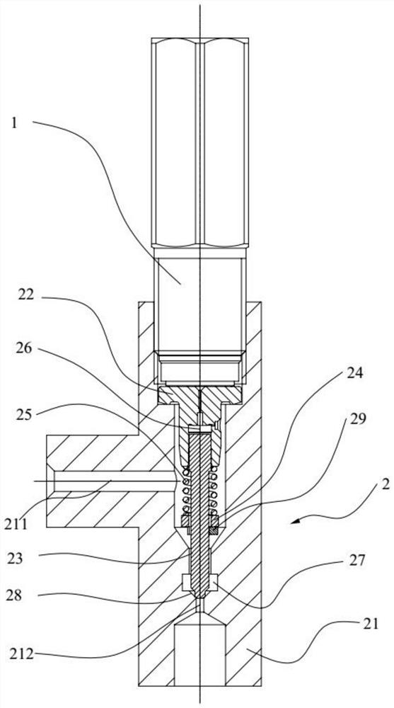
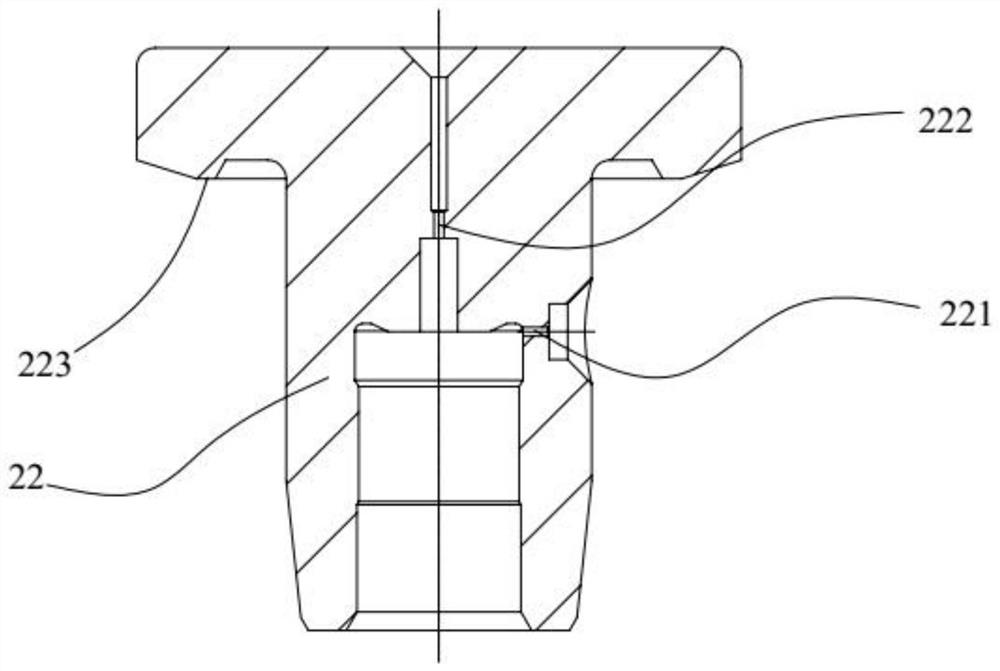
The invention belongs to the technical field of hydraulic pressure, and discloses a flow adjusting device and a common rail system. The flow adjusting device comprises a pressure limiting valve and a flow amplifying mechanism, the flow amplifying mechanism comprises a valve body, and an oil inlet channel and an oil outlet channel which communicate with each other are arranged on the valve body. The pressure limiting valve penetrates through the valve body in a sealed mode and abuts against a valve sleeve, an oil inlet throttling hole and an oil outlet throttling hole are formed in the valve sleeve, the oil inlet throttling hole communicates with the oil inlet channel, the oil outlet throttling hole selectively communicates with the pressure limiting valve, and the flow of the oil inlet throttling hole is smaller than that of the oil outlet throttling hole. One end of a valve element penetrates through the valve sleeve, the other end of the valve element penetrates through the valve body, a first volume cavity is formed between the valve element and the valve sleeve, the first volume cavity communicates with the oil inlet throttling hole and the oil outlet throttling hole, a second volume cavity is formed between the valve element and the valve body, and the valve element can slide relative to the valve body so that the valve element can selectively block the oil outlet channel. The flow adjusting device can meet the requirements for large flow and high pressure at the same time.

Description

Technical field [0001] The present invention relates to the field of hydraulic technology, and more particularly to a flow rate adjustment device and a common rail system. Background technique [0002] The restriction valve is a device that limits the pressure. When the pressure reaches the working pressure, the restriction valve is exhausted or draining oil through the exhaust port to avoid the continuation of the pressure. [0003] The finishing valve has two forms. The first pressure limiting valve is used for the engine main oilway, which is suitable for a low pressure system. The pressure valve sealing has a large diameter, although the amount of discharge is large, but the opening pressure is low; the second pressure pressure The valve is used in the fuel injection system, although the opening pressure is high, but due to the limitation of the throttle, the amount of discharge is small, and is not suitable for large flow common rail systems. These two restriction valves can...

Claims


Application Information

Patent Timeline
IPC IPC(8): F02M63/00F02M55/02
CPCF02M63/0028F02M63/0056F02M63/005F02M55/025
Inventor 何浩然唐继响王红磊苏晓东
Owner FAW JIEFANG AUTOMOTIVE CO
Learn More