
Optical system of liquid crystal projector

A technology for optical systems and projectors, which is applied in the field of optical systems and can solve problems such as size reduction

Inactive Publication Date: 2003-02-19
LG ELECTRONICS INC
View PDF1 Cites 8 Cited by
  • Summary
  • Abstract
  • Description
  • Claims
  • Application Information

AI Technical Summary

Problems solved by technology

However, the two-layer structure optical system also uses a large number of optical elements, which limits the reduction of its size.

Method used

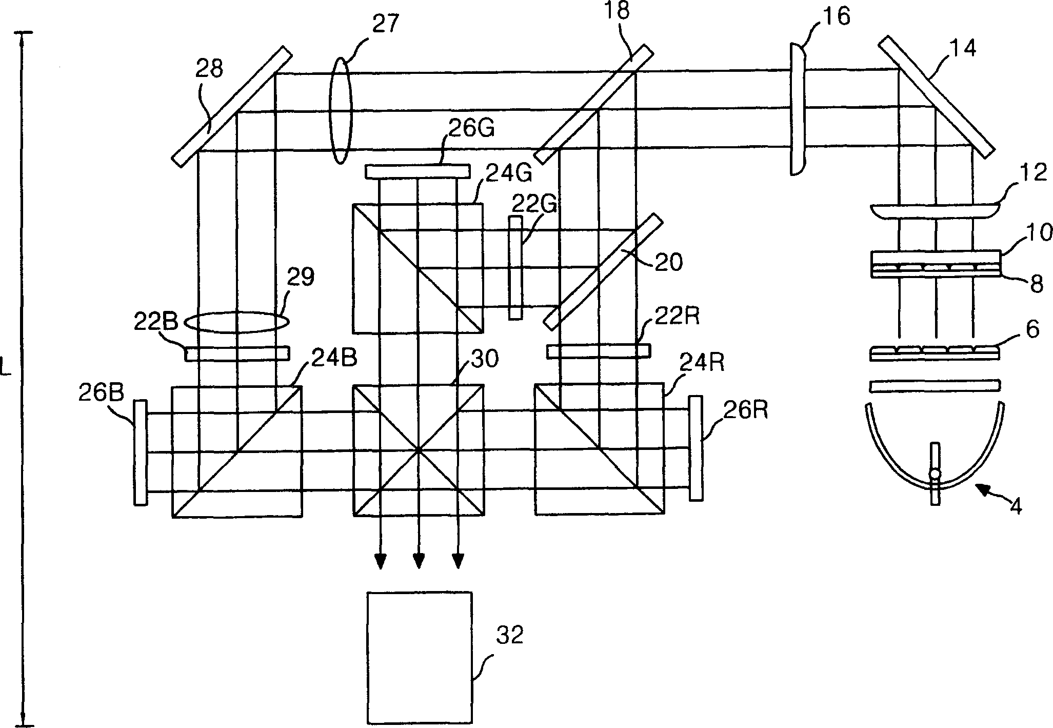
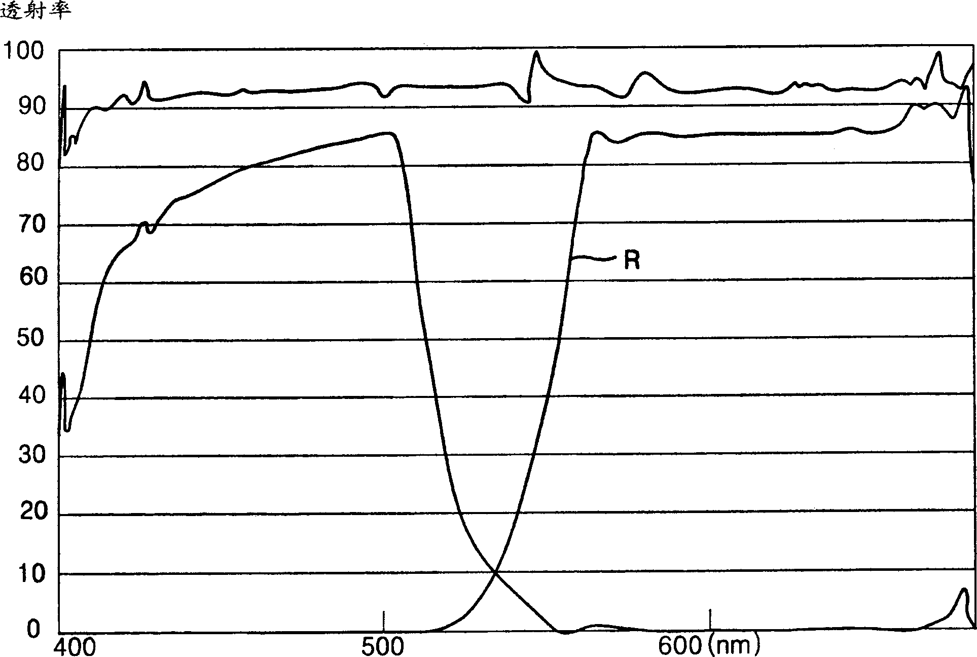

Image

  • Optical system of liquid crystal projector
  • Optical system of liquid crystal projector
  • Optical system of liquid crystal projector

Examples


Embodiment Construction

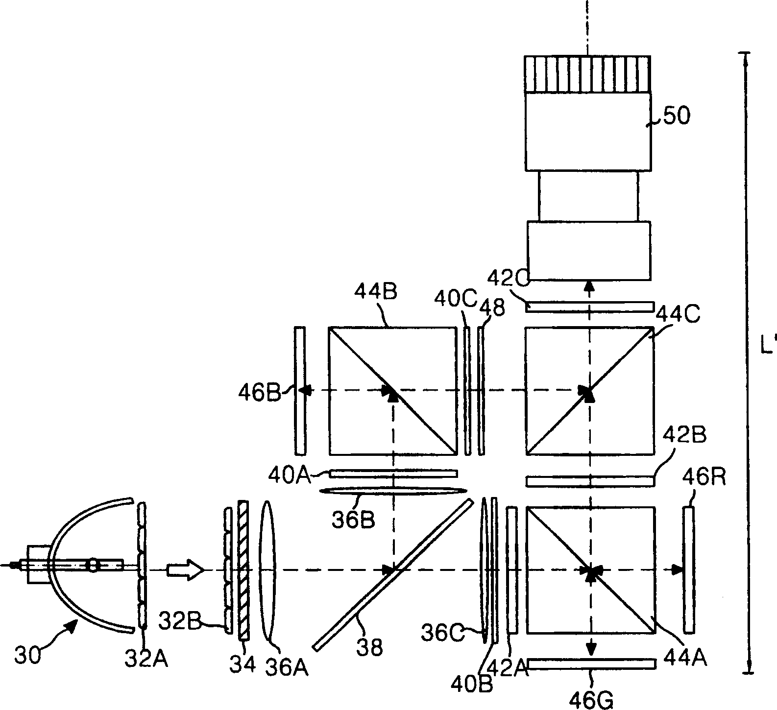
[0034] refer to figure 2 , shows an optical system of a liquid crystal projector according to an embodiment of the present invention.

[0035] The optical system includes three reflective LCD panels 46R, 46G and 46B for displaying images, an illumination unit for uniformly and effectively irradiating the white light from the light source 30 onto the LCD panels 46R, 46G and 46B, and a The color splitter is used to spatially separate the white light from the lighting unit into red, green and blue light and make the separated color light reach the reflective LCD panel 46R, 46G and 46B, and a light combining unit is used to combine to obtain the light from Three color lights reflecting the image information of the LCD panel 46R, 46G and 46B, and a projection lens 50 for enlarging and projecting the combined image.

[0036] The lighting unit is composed of a light source 30 , first and second FELs 32A and 32B, and a PBS array 34 . The color splitter includes a dichroic mirror 38...


PUM


Abstract

An optical system of a liquid crystal projector that is capable of reducing a full length of the optical system including three reflective liquid crystal display panels. In the system, an illuminating unit allows a white light generated from a light source to have any one linear polarized light and a uniform light distribution. A color separator separates the white light from the illuminating unit in accordance with a wavelength band to obtain a first color light, and polarization-converts the remaining lights in accordance with a wavelength band and then separates them into second and third color lights depending on their polarization components. First to third liquid crystal display panels uses the first to third color lights from the color separator to implement first to third color pictures, respectively. A picture combining unit combines the first to third color lights having acquired picture information from the first to third liquid crystal display panels. A projection lens unit projects the combined picture from the picture combining unit onto a screen on an expanded scale. Accordingly, the optical system can reduce the number of optical elements.

Description

technical field [0001] The present invention relates to a liquid crystal projector, and more particularly to an optical system of a liquid crystal projector capable of minimizing the size of the optical system and the number of optical elements using three reflective liquid crystal displays. Background technique [0002] Now, attention has been paid to flat panel displays capable of replacing cathode ray tube displays having screen and large system size limitations and capable of realizing thin thickness and large-scale screens. Flat panel displays include projectors that project images of a small area onto a large screen at an enlarged scale. [0003] A projector employs a cathode ray tube or a liquid crystal display (LCD) as a display device for realizing a small-scale image. Recently, LCDs are mainly used to keep up with the trend of thinner thickness of projectors. Typically, liquid crystal projectors use transmissive or reflective LCDs. The d...

Claims


Application Information

Patent Timeline
Patent Type & Authority Applications(China)
IPC IPC(8): G03B21/00H04N9/31
CPCH04N9/3197H04N9/3105G02B27/1026G02B27/145G03B21/00
Inventor 权纯炯罗万湖
Owner LG ELECTRONICS INC
Learn More