
Charging equipment fo r non-contact power transmission, power absorbing equipment and charging system

A technology for charging equipment and power transmission, applied in electromagnetic wave systems, battery circuit devices, circuits, etc., can solve the problems of magnetic coupling reduction, magnetic core energy loss, magnetic core saturation, etc.

Inactive Publication Date: 2003-02-19
弗里沃仪器制造有限责任公司
View PDF0 Cites 3 Cited by
  • Summary
  • Abstract
  • Description
  • Claims
  • Application Information

AI Technical Summary

Problems solved by technology

This results in loss of core energy and saturation of the core
In addition, the magnetic core of the same size will also cause the problem of reduced magnetic coupling when the two pole faces are displaced from each other.

Method used


Image

  • Charging equipment fo r non-contact power transmission, power absorbing equipment and charging system
  • Charging equipment fo r non-contact power transmission, power absorbing equipment and charging system
  • Charging equipment fo r non-contact power transmission, power absorbing equipment and charging system

Examples


Embodiment Construction

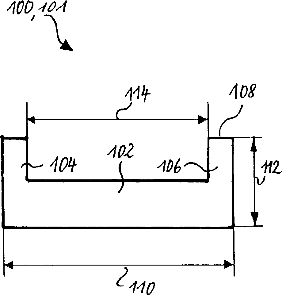
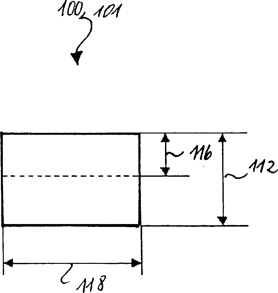
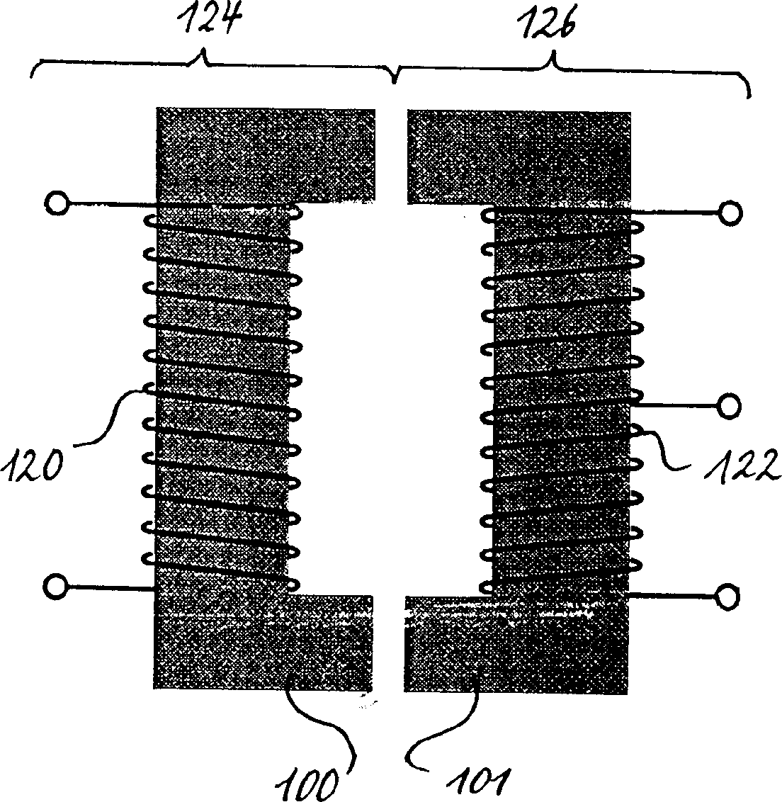
[0014] figure 1 and figure 2 is a side view of a ferrite core 100, which theoretically can be used for both the primary side and the secondary side according to the present invention. The ferrite core 100 is substantially U-shaped because this shape allows for the greatest possible coupling between the primary and secondary sides. The ferrite core 100 includes a base region 102 and two arm regions 104 , 106 each having a pole face 108 . According to the present invention, winding coils (only in image 3 shown in ) is disposed on the base region 102 of the U-shaped ferrite core. In order to keep the magnetic coupling between the two pairs of pole faces of the ferrite core 100 small, it is important that the ferrite core 100 is flat relative to its length. From figure 1 It can be seen that the length 110 of the base region is 2 to 3 times the projecting length 112 of the arm regions 104, 106, and the ratio of the inner length 114 of the base region 102 to the inner length ...


PUM


Abstract

The present invention relates to a charging unit used for a contactless transfer of electric power to a mobile unit, a complementary power absorbing device and a charging system. The charging unit transfers by means of an alternating magnetic field electric power from at least one primary winding to at least one secondary winding arranged in said mobile unit, and comprises a substantially U-shaped ferrite core which comprises a base area and two leg areas, each provided with a pole face, and which has the primary winding arranged thereon. In order to provide a charging unit for a contactless transfer of electric power to a mobile unit, an associated power absorbing device and a charging system, which permit an improved magnetic coupling between the primary side and the secondary side and consequently an improved power transfer, the primary winding is arranged on the base area of the U-shaped ferrite core. According to an advantageous further development, the base area of the U-shaped ferrite core can be longer than the leg areas so that the ferrite core has a substantially elongate structural design.

Description

technical field [0001] According to the general terms of claims 1, 4 and 7, the invention relates to a charging device for contactless power transfer to mobile devices, an auxiliary power absorbing device and a charging system. Background technique [0002] Contactless power transfer based on the principle of inductive coupling can be used, for example, in mobile electronic devices, such as mobile radio devices, rechargeable batteries for cordless telephones, and it can also be used in the field of automation engineering. For such a contactless power transmission, the power is transferred inductively from a charger to a mobile device via an alternating magnetic field, as known for example from Offenlegungsschrift DE 197 41 279 A1. The primary and secondary coils are wound on the side arms of two roughly U-shaped ferrite cores. Other known shapes are rod or E-shaped ferrite cores. In conventional charging systems for contactless power transfer, the primary and secondary sid...

Claims


Application Information

Patent Timeline
IPC IPC(8): H01F38/14H02J7/02
CPCH02J7/025H01F38/14H02J50/10
Inventor 阿诺·莱恩哈德拉尔夫·施罗德
Owner 弗里沃仪器制造有限责任公司
Learn More