LED module

A technology of LED module and collimator, which is applied in the direction of instruments, lighting and heating equipment, semiconductor devices of light-emitting components, etc., can solve the problem of limited maximum size of LED modules, etc.

Inactive Publication Date: 2003-03-19
SIGNIFY HLDG BV
View PDF6 Cites 64 Cited by
  • Summary
  • Abstract
  • Description
  • Claims
  • Application Information

AI Technical Summary

Problems solved by technology

Due to this, the maximum size of

Method used


Image

  • LED module
  • LED module
  • LED module

Examples


Embodiment Construction

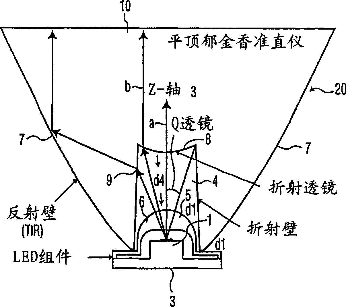
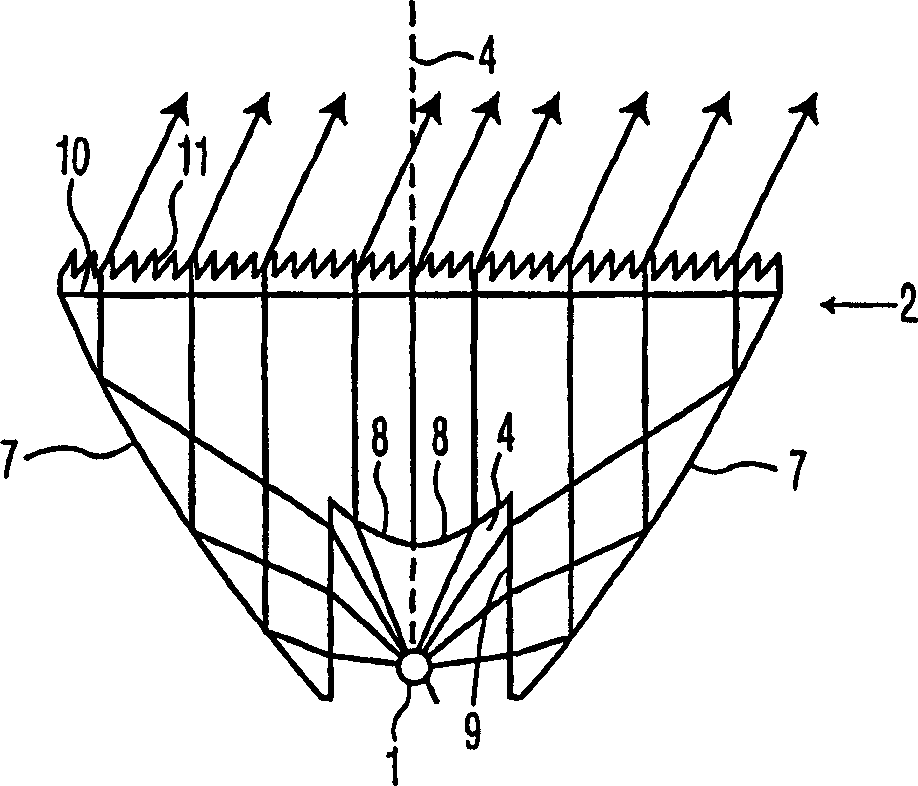
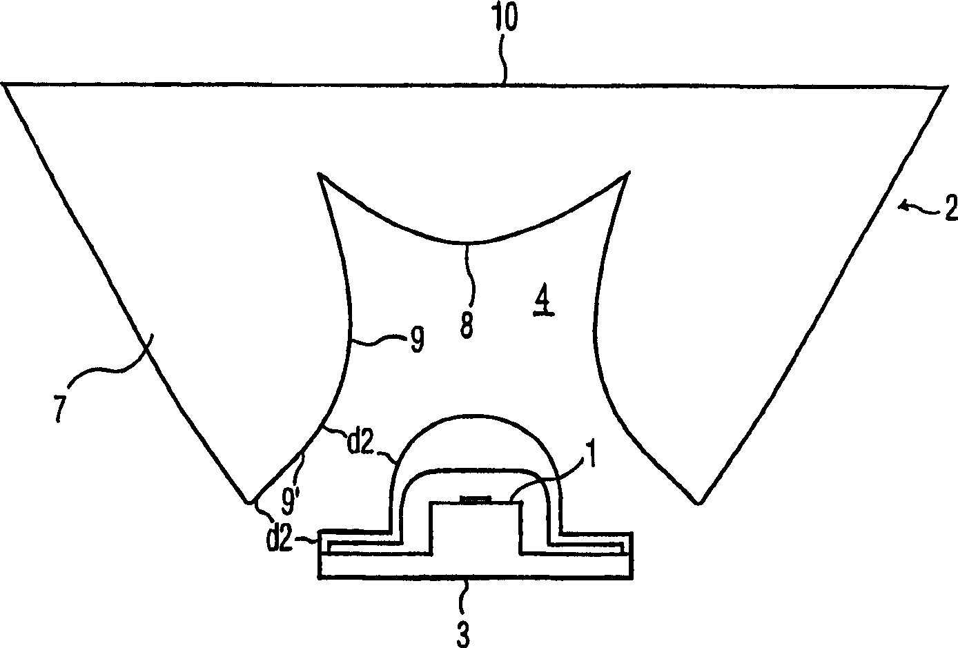
[0037] refer to Figure 1A with 1B , which respectively illustrate the prior art and the above-mentioned collimating element described in WO-A00 / 42,062, an LED light source or module 1 is associated with an embodiment of the collimating element 2 . The LED 1 is placed in the recess 4 of the bowl-shaped collimating element 2 . The collimating element 2 has an optical axis 3 and comprises an element body 4 for emitting light during operation. exist Figure 1A In the example shown, the body 5 of the LED 1 is provided with a light-transmitting housing 6, for example in the form of a lens. exist Figure 1B In the example, the LED is represented by a dot. The collimating element 2 has an optical axis 3 which coincides with the optical axis 3 of the LED 1 . The shape of the collimating element 2 is chosen such that the light emitted from the LED 1 is emitted by the optical system in a direction parallel to the optical axis 3 of the collimating element 2 . The shape of the curved...


PUM


Abstract

An LED module that includes an LED (light-emitting diode) (1) and a rotationally symmetrical, bowl-shaped collimator lens (2) is provided. The collimator lens has an inner refractive wall (9), an outer reflective wall (7), a first surface (8) having an entrance aperture (3) with a recess (4) in which the LED is situated and which collimator lens is also provided with a second surface (10) from which light generated by the LED emerges, the normal to the surface extending substantially parallel to the axis of symmetry of the lens, and the LED module also includes one or more of the following structures : (1) a conic wall portion of the recess (4) of the inner refractive wall (9) at the entrance aperture (3) that includes a curved portion (9'), and an outer reflective wall (7) so configured in accordance with the structure of the inner refractive wall (9) to achieve substantial collimation of a source of light (1) at the entrance aperture; and/or (2) a first surface (8) of the lens (2) that is recessed away from the LED source (1); and/or (3) two surfaces (8), (11) of said refractive wall (9) between which the refractive function of said refractive wall (9) is divided. The LED module offers an improvement in the performance of the Flat top Tulip Collimator known in terms of reduced size, beam divergence, beam uniformity, and to some degree efficiency. Moreover, it allows a wider variety of choices in optimizing various performance characteristics, and this in turn allows more flexibility in the structure design.

Description

technical field [0001] The present invention relates to an LED module comprising an LED (Light Emitting Diode) and a rotatably symmetrical bowl-shaped collimator lens, the collimator lens is provided with a recess for accommodating the LED, and the collimator lens is provided with a flat surface from which This plane emits the light generated by the LED, the normal of which runs substantially parallel to the axis of symmetry of the lens. The invention also relates to a lighting fixture provided with some of said LED modules. Background technique [0002] LED modules of the type mentioned in the opening paragraph are known per se. Such an LED module is described, for example, in the English abstract of Japanese patent application JP61-147,585. The LED module consists of an LED mounted on a base and seated in the recess of a bowl-shaped collimator lens. This lens is rotationally symmetric in shape and has an associated axis of symmetry. The position ...

Claims


Application Information

Patent Timeline
IPC IPC(8): F21V5/04F21V7/00G02B3/00G02B6/42H01L33/54H01L33/58H01L33/60
CPCF21V5/04H01L33/54G02B3/00G02B6/4206F21V7/0091H01L33/58F21Y2101/02H01L33/60F21Y2115/10
Inventor T·M·马沙尔M·D·帕斯利
Owner SIGNIFY HLDG BV
Why Eureka
Try Eureka