
Nonvolatile internal storage reliability test method and circuit

A non-volatile, testing method technology, applied in the direction of static memory, instrument, etc., can solve the problems of indistinguishable state "1, storage unit storage information failure, storage unit information cannot be read out correctly, etc.

Inactive Publication Date: 2003-03-26
MACRONIX INT CO LTD
View PDF0 Cites 10 Cited by
  • Summary
  • Abstract
  • Description
  • Claims
  • Application Information

AI Technical Summary

Problems solved by technology

The increase of the critical voltage will cause the increase of the leakage current (leakage current), and will make the stored information of the memory cell invalid
For example, when the state "1" is lower than a certain critical voltage, the state "1" or the state "0" cannot be distinguished due to the increase of the critical voltage; that is, the information stored in the memory cell cannot correct readout

Method used


Image

  • Nonvolatile internal storage reliability test method and circuit
  • Nonvolatile internal storage reliability test method and circuit
  • Nonvolatile internal storage reliability test method and circuit

Examples


Embodiment Construction

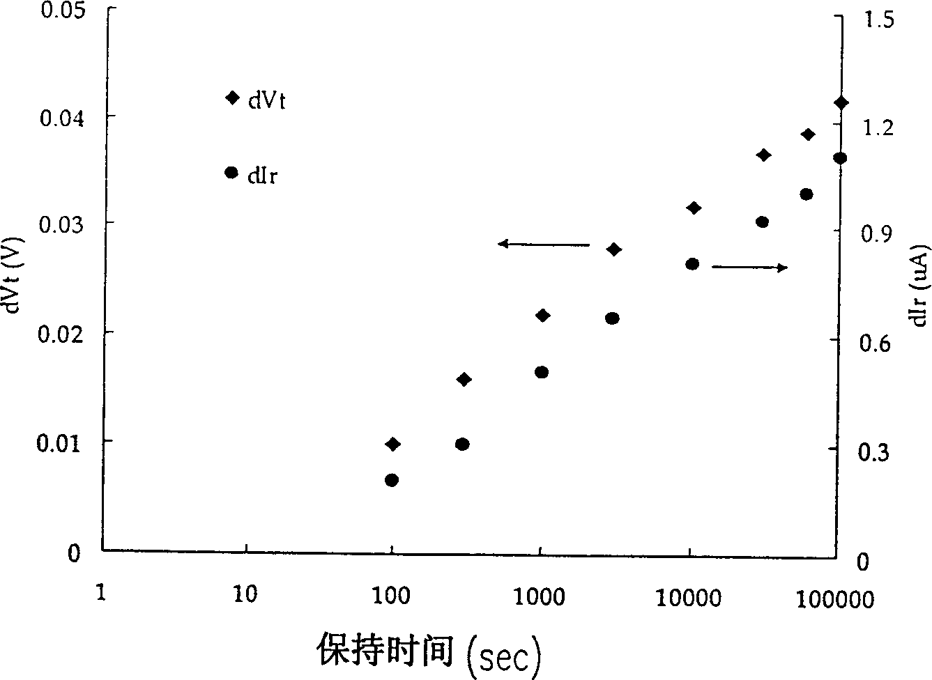
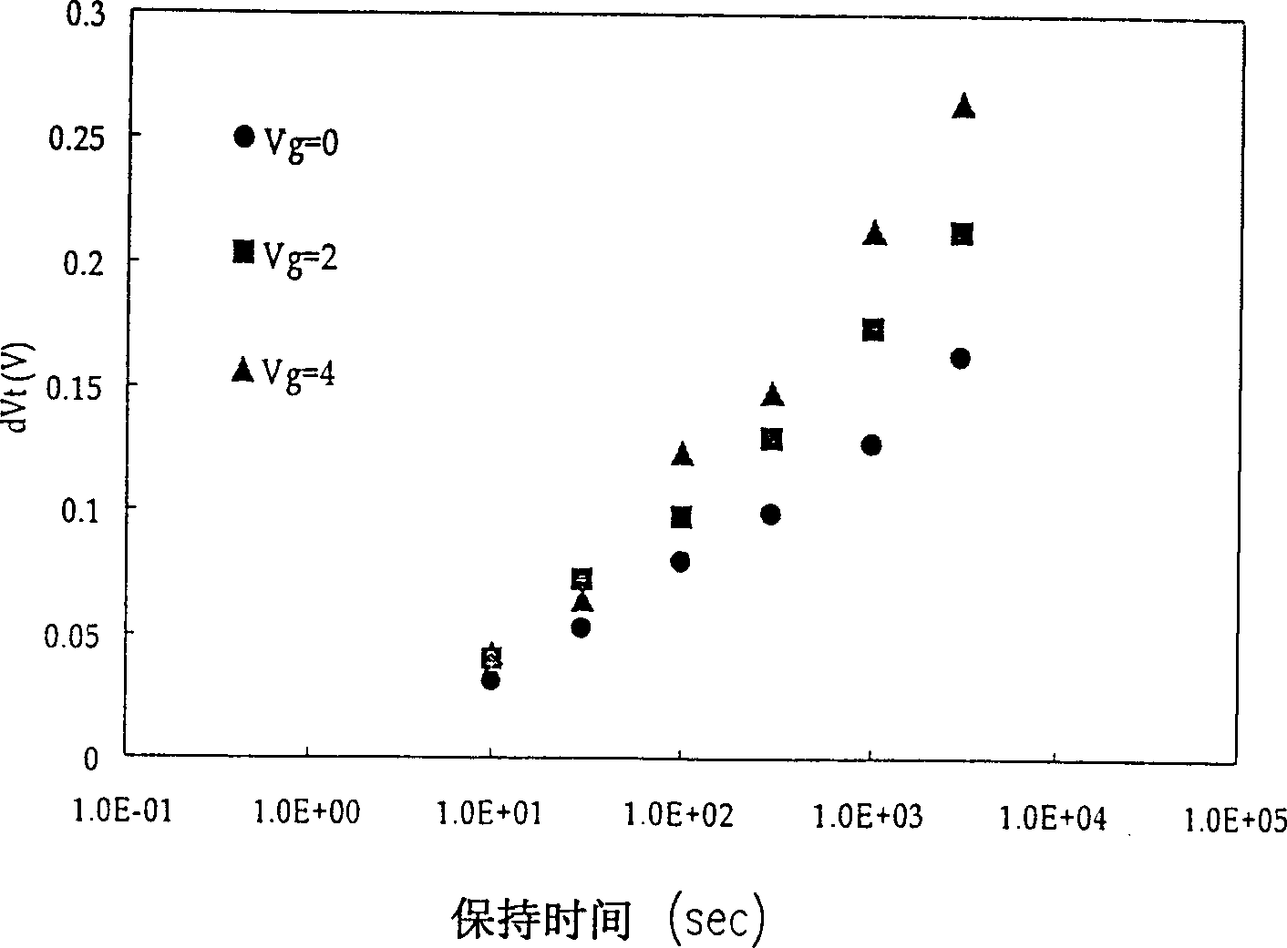
[0018] The threshold voltage drift (threshold drift) and the read current drift (read current drift) of the non-volatile memory with the insulating trap layer will increase as the retention time of the memory cell increases. And this drift phenomenon is related to the retention time The logarithm of is approximately a linear relationship. The present invention utilizes the physical phenomenon of this offset to perform accelerated testing of the reliability of the storage unit.

[0019] figure 2 is a plot of threshold voltage shift versus read current shift and hold time. Such as figure 2 As shown, first of all, look at the shift phenomenon of the threshold voltage, which is represented by a diamond mark in the figure. As the holding time increases, it can be seen from the figure that the offset of the critical voltage also increases. For example, when the hold time is 100 seconds, the threshold voltage offset dVt is about 0.01V, and when the hold time reaches 100000 secon...


PUM


Abstract

The method includes the following steps. The relation curve between the grid voltage and the attenuation rate of the reading current is decided. The actual grid voltage and its relevant attenuation rate of the reading current are predicted. The accelerated test grid voltage and the test time relevant to the actual grid voltage are solved from the said relation curve. The test is carried out continuously in the test time number the accelerated test grid voltage in order to measure the reading current related as well as determine whether the memory is in effect or not. Thus, the reliability testing for the non-volatile memory is completed.

Description

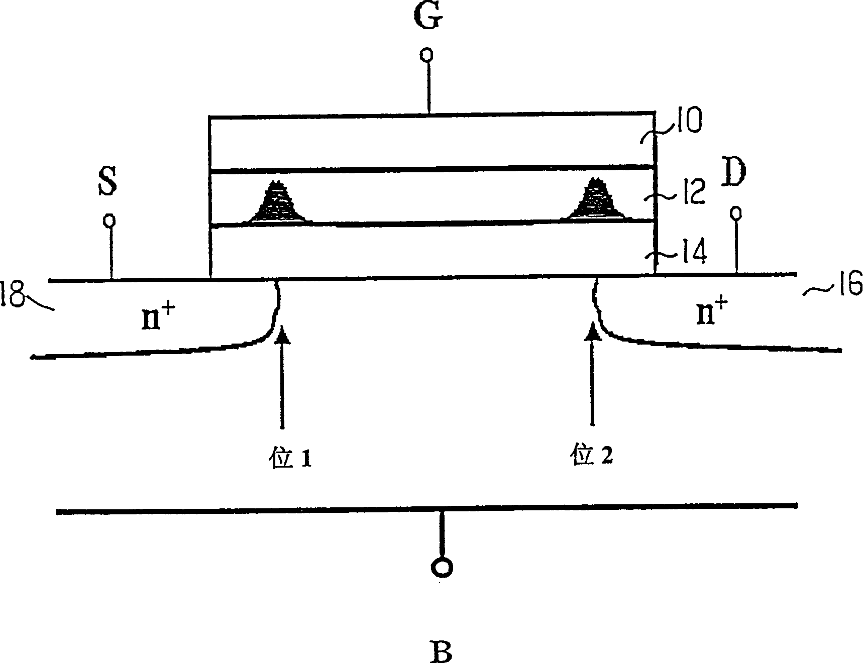
technical field [0001] The invention relates to a test circuit and method of a non-volatile memory, and in particular to a method and circuit for a qualification test of a non-volatile memory with a trapping layer. Background technique [0002] Non-volatile memory (non-volatile memory), such as flash memory (Flash), generally has a gate structure currently used with a control gate and a floating gate. The gate is used to store charge. Under this structure, because the floating gate is a conductor made of polysilicon, when the memory cell is programmed, the electrons injected into the floating gate will be uniformly distributed in the floating gate. Therefore, this memory cell with a floating gate structure can only store one bit. Afterwards, a memory cell structure in which an insulator is used to replace a floating gate has been proposed. When an insulator is used to confine electrons, the electrons can be partially constricted, so that the storage of two bits can be ach...

Claims


Application Information

Patent Timeline
IPC IPC(8): G11C29/00
Inventor 蔡文哲邹年凯黄兰婷汪大晖
Owner MACRONIX INT CO LTD
Learn More