Pneumatic activator

A pneumatic controller and air source technology, applied in engine control, machine/engine, mechanical equipment, etc., can solve problems such as frying cans

Inactive Publication Date: 2003-04-02
沈传良
View PDF0 Cites 6 Cited by
  • Summary
  • Abstract
  • Description
  • Claims
  • Application Information

AI Technical Summary

Problems solved by technology

If you keep inflating when you stop using the gas, it will cause dangers such as frying the tank

Method used


Image

  • Pneumatic activator
  • Pneumatic activator
  • Pneumatic activator

Examples


Embodiment Construction

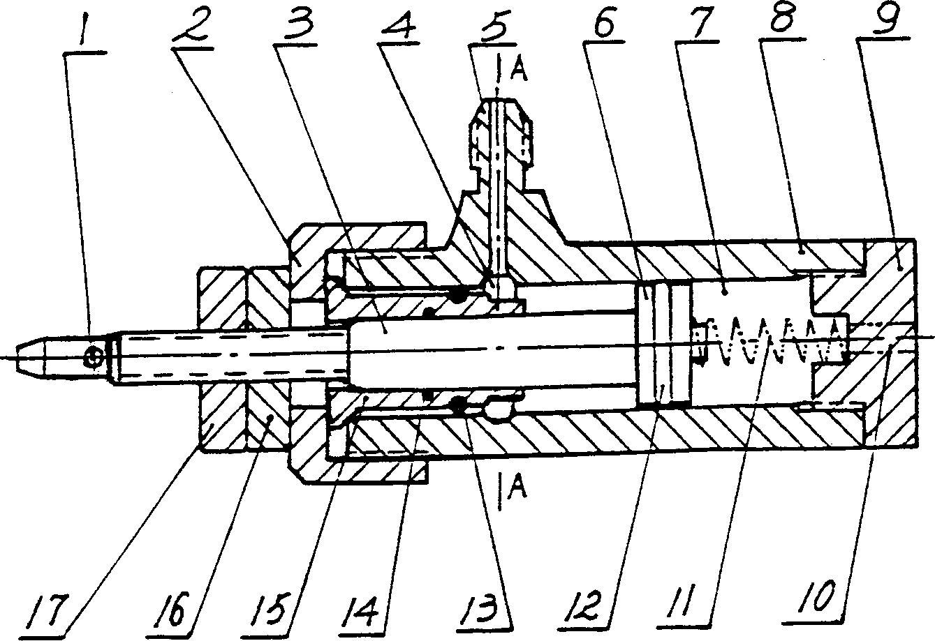
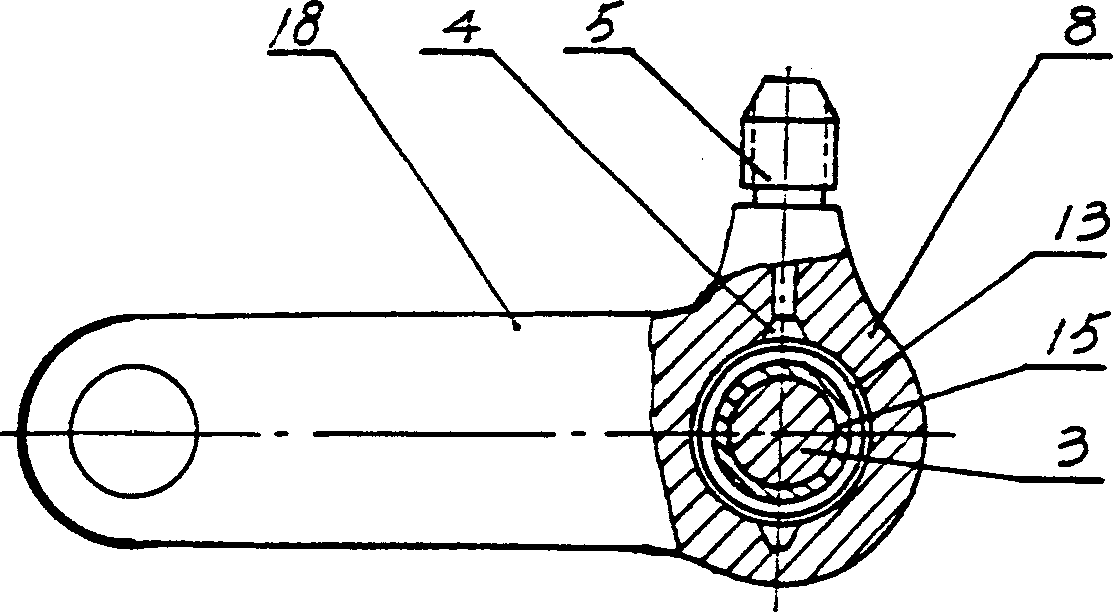
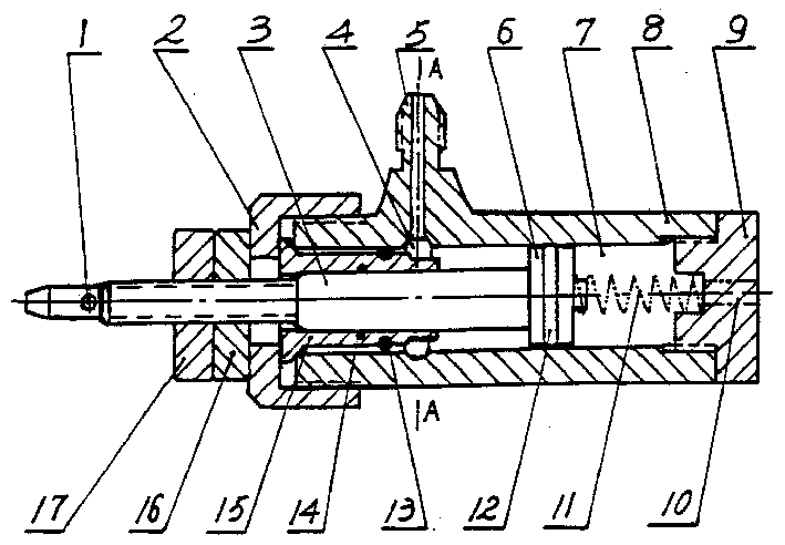
[0007] The present invention relates to a pneumatic controller used in internal combustion engine-driven air compressor equipment. There is a cylinder body 8 which can be made into a cylindrical shape, a piston 6 and a piston rod 3 are installed in the cylinder body, and a cylinder cover 15 is arranged outside the piston rod. , the piston 6 and the cylinder head 15 form the cylinder cavity in the cylinder body, and the cylinder head 15 and the cylinder body 8 have fixing devices, figure 1 Shown this fixing device is nut 2, but also can not need nut, and with fixed pin or various related fasteners etc. Piston rod 3 outer heads are shaped on internal-combustion engine throttle backguy connecting hole 1, are shaped on the air source connector 5 that connects air storage tank at cylinder body 8 outer walls, and these two are two places that this pneumatic controller externally connects. The inner hole of the air source connector 5 is connected to the cylinder cavity, and the inner...


PUM


Abstract

A pneuamtic controller for IC engine (diesel engine or gasoline engine) to drive air compressor is composed of a cylinder body, piston, piston rod and cylinder cover. A hole for linking the pull string of throttle if IC engine is made on the external end of piston. An adapter to air tank as air source is made on the external surface of cylinder. When the compressed air is normally consumed, the pressure in air tank is normal. If the air consumption is stopped, the pressure in air tank is increased to push piston to move. The piston rod moves inward to pull the pull string of throttle, so decelerating the IC engine and in turn the air compressor to autoamtically regulate the output of air compressor.

Description

technical field [0001] The invention relates to a controller, which is mainly used in an air compressor driven by an internal combustion engine. The air pressure of the air storage tank of the air compressor is used to change the throttle cable of the internal combustion engine to automatically adjust the operation status of the internal combustion engine. Background technique [0002] The air compressor is generally driven by a motor, but in the wild, especially in remote mountainous areas, an air compressor is used to open rocks, etc., and only an internal combustion engine (such as a diesel engine) is used to drive it. The use of compressed air often has gaps. When the gaps are not used, the internal combustion engine cannot be turned off and completely shut down, otherwise it will be troublesome to start. If you keep inflating when you stop using the gas, it will cause dangers such as frying the tank. Therefore, when the air compressor is driven b...

Claims


Application Information

Patent Timeline
IPC IPC(8): F02B63/06F02D33/00
Inventor 沈传良
Owner 沈传良
Why Eureka
Try Eureka