Yarn twisting piecing device
A technology of yarn and joint position, which is applied in jointing devices, spinning machines, transportation and packaging, etc. It can solve the problems of large structural space and inconvenient operation, and achieve the effect of strong yarn connection
- Summary
- Abstract
- Description
- Claims
- Application Information
AI Technical Summary
Problems solved by technology
Method used
Image

Examples
Embodiment Construction
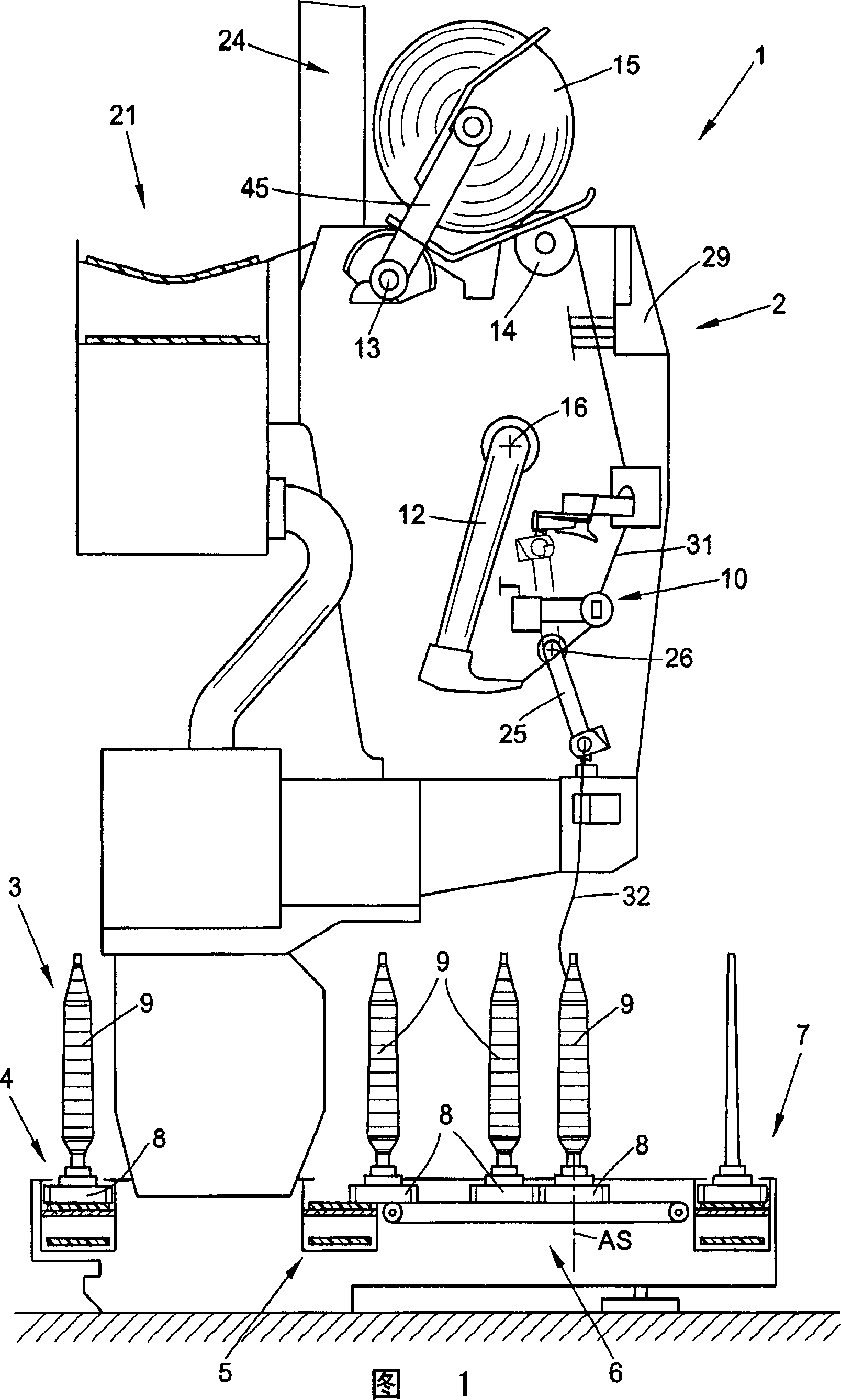
[0028] In FIG. 1 , an embodiment of a spinning machine for producing cross bobbins, ie an automatic cross-winding winder, is shown schematically in side view, generally designated 1 . This automatic cross-winding winder generally has many identical working parts at its rear (not shown in the figure), which is exactly the winding head 2 in the existing case.
[0029] On the winding head 2, as is well known and therefore not described in detail here, the bobbin 9 produced by the ring spinning machine is rewound into a large roll cross bobbin 15, which when completed, is crossed bobbin 15 by means of an automatic working Auxiliary devices and preferably a cross bobbin changer (not shown) are transferred to a machine longitudinal cross bobbin conveying device 21 and conveyed to a bobbin loading station or similar device located at the end of the machine.
[0030] Furthermore, the cross-winding automatic winder 1 has a logistics device as bobbin and tube transport system 3 . In th...
PUM
 Abstract
Description
Claims
Application Information
 - R&D
- Intellectual Property
- Life Sciences
- Materials
- Tech Scout
- Unparalleled Data Quality
- Higher Quality Content
- 60% Fewer Hallucinations
Browse by: Latest US Patents, China's latest patents, Technical Efficacy Thesaurus, Application Domain, Technology Topic, Popular Technical Reports.
© 2025 PatSnap. All rights reserved.Legal|Privacy policy|Modern Slavery Act Transparency Statement|Sitemap|About US| Contact US: help@patsnap.com