
Hydraulic elevator system of improvement running performance by accumulator

A technology of elevator system and operation performance, which is applied in the field of hydraulic elevator system, and can solve the problems of hydraulic pump output flow pulsation, motor rotation instability, and motor actual speed out of sync.

Inactive Publication Date: 2003-04-30
SHANGHAI MITSUBISHI ELEVATOR CO LTD
View PDF2 Cites 10 Cited by
  • Summary
  • Abstract
  • Description
  • Claims
  • Application Information

AI Technical Summary

Problems solved by technology

[0008] In all the disclosed technical schemes of hydraulic elevator systems using speed-regulating motors, there is a common problem, that is, due to oil leakage in the system, the rotational speed of the motor is not synchronized with the actual speed of the elevator. Vibration and shock of the elevator manifested in the start-up process
However, before the car starts to move, the fluid stiffness from the outlet of the hydraulic pump to the inlet side of the solenoid valve is very large, and the instability of the rotation of the motor at low speed and the pulsation of the output flow of the hydraulic pump make pressure adjustment very difficult.

Method used


Image

  • Hydraulic elevator system of improvement running performance by accumulator
  • Hydraulic elevator system of improvement running performance by accumulator
  • Hydraulic elevator system of improvement running performance by accumulator

Examples


Embodiment Construction

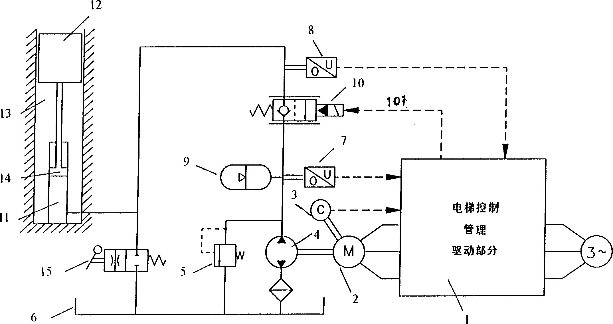
[0016] figure 1 It is a schematic diagram of the hydraulic elevator system and its control device using an accumulator to improve the running performance of the present invention. As shown in the figure, the hydraulic elevator system using an accumulator to improve running performance in the present invention includes an elevator shaft 13, an oil cylinder 11 buried in the bottom pit of the elevator shaft 13, pressure oil injected into the oil cylinder 11, and a piston 14 supported by the pressure oil , the car 12 fixed on the upper end of the piston 14, the motor 2, the hydraulic pump 4, the elevator control and management connected with the motor 2, the driver 1 and the rotary encoder 3, the solenoid valve 10 connected with the hydraulic pump 4 and the oil cylinder 11, respectively The pressure transmitters 7 and 8 for measuring the oil pressure at the inlet and outlet of the electromagnetic valve 10, and the hydraulic pump 4 and the oil cylinder 11 are connected to the oil t...


PUM


Abstract

A hydraulic elevator system using energy accumulator to improve its running performance features that a drive motor whose speed is regulated by changing voltage and frequency is used to change the flow of hydraulic pump. It is composed of cage, asynchronous motor, hydraulic pump electromagnetic valve, oil cylinder, hydraulic energy accumulator and two pressure transducers, which can measure and feed back the pressure of hydraulic pump and oil cylinder to form a pressure closed-loop system for conpensating leakage.

Description

technical field [0001] The invention relates to a hydraulic elevator system which uses an accumulator to improve running performance. It is a hydraulic elevator system which changes the outlet flow rate of a hydraulic pump through variable voltage, variable frequency, and speed regulation to drive a motor to realize stable startup of an elevator car. Background technique [0002] The motor speed control system is applied to the hydraulic elevator system, which can greatly improve its efficiency, and is considered as an energy-saving hydraulic elevator system. A constant flow hydraulic pump provides pressure oil to the oil cylinder through a solenoid valve to move the car up and down. The above solenoid valve usually operates as a one-way stop valve to prevent safety accidents when the elevator goes down, but when the solenoid valve is electromagnetically excited, It can be reversed to make the elevator go down. Due to the weight of the car, the pressure oil in the oil cylin...

Claims


Application Information

Patent Timeline
IPC IPC(8): B66B1/04
CPCY02B50/148Y02B50/146Y02B50/00
Inventor 朱思中王兴琪黄维钢
Owner SHANGHAI MITSUBISHI ELEVATOR CO LTD
Learn More