
Circuit and method for quick eliminating off afterimage of liquid crystel display

A liquid crystal display, fast technology, applied in the direction of static indicators, instruments, etc., can solve the problems of delayed discharge time, poor discharge efficiency, etc.

Inactive Publication Date: 2003-05-28
CHEERTEK
View PDF0 Cites 19 Cited by
  • Summary
  • Abstract
  • Description
  • Claims
  • Application Information

AI Technical Summary

Problems solved by technology

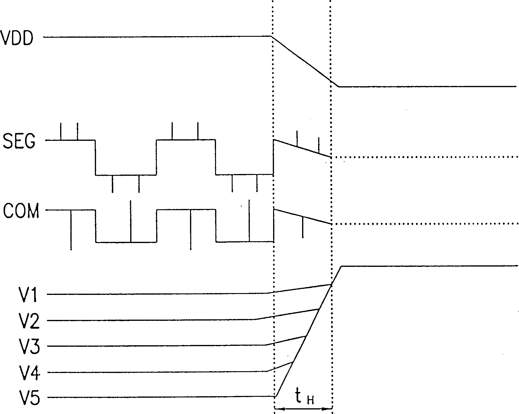
However, this method has the disadvantages of delaying the discharge time due to the continuous supply of voltages V1 to V5 and poor discharge efficiency when V5 is greater than VSS.

Method used


Image

  • Circuit and method for quick eliminating off afterimage of liquid crystel display
  • Circuit and method for quick eliminating off afterimage of liquid crystel display
  • Circuit and method for quick eliminating off afterimage of liquid crystel display

Examples


Embodiment Construction

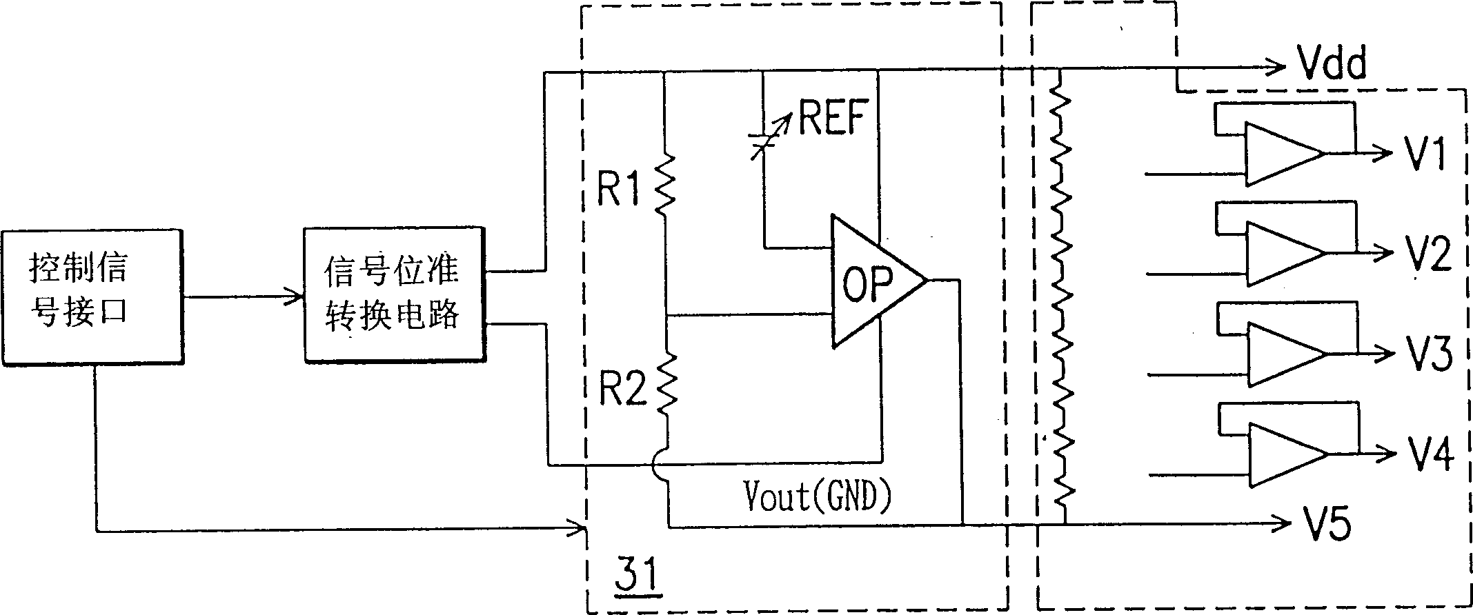
[0027] refer to Figure 7 , is a schematic circuit diagram of the invention, which is based on Figure 5 Improved. exist Figure 7Among them, the circuit includes: a manual selector ERPIN, an automatic detection circuit 70, an OR gate 75, a fast discharge circuit 76 and an LCD power controller 77. The manual selector can be a control signal ERPIN connected to an external clear to output a manual control signal MDRV from the input. The automatic detection circuit 70 is partially identical to the Figure 5 Part 50 includes a detection circuit 71 to detect the activation signal. The detection circuit 71 can be made up of an OR gate (ORgate), which is used to activate the automatic detection circuit in two states when the circuit is not yet closed (at this time, Power_down=low) and the stabilizing capacitor is stable (at this time, Start_up=low) 70. After activation, the circuit 70 uses a comparator 72 to compare a reference voltage VREF from a reference voltage source 73 wi...


PUM


Abstract

A method for quickly eliminating the shutdown afterimage of LCD includes receiving control signal, comparing the first with the second reference voltage, and outputting start signal to the controllerof LCD power supply and fast discharge circuit for fast discharge if the first reference voltage is less than or equal to the second one. Its circuit is composed of manual selector, automatic detector, selection switch, fast discharge circuit and controller of LCD power supply.

Description

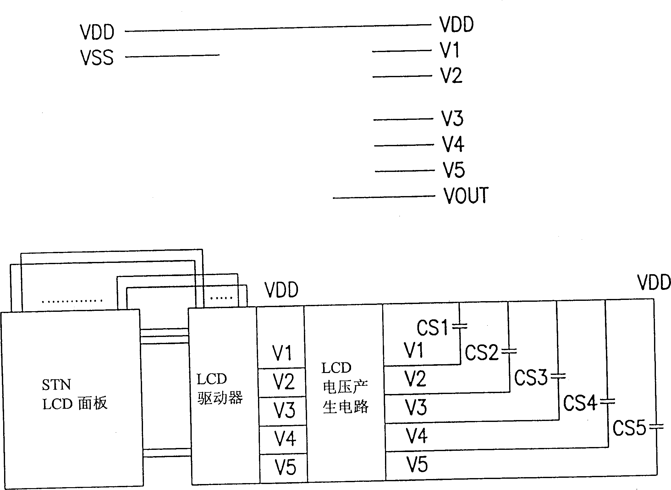
technical field [0001] The present invention relates to a processing circuit and method for a display power-off residual image (fast liquid crystal display (LCD) power-off residual image suppression circuit and a method thereto), in particular to a circuit for quickly eliminating a liquid crystal display (LCD) power-off residual image and methods, particularly applicable to cellular phones. Background technique [0002] In a liquid crystal panel control circuit, such as a Super Twist Nematic (STN) liquid crystal panel, a voltage generating circuit generates a driving voltage (for example: V 1 , V 2 , V 3 , V 4 and V 5 ), and using the supply voltage (V DD ), V 1 , V 2 , V 3 , V 4 and V 5 The voltage changes at different times cause the liquid crystal to produce different changes in brightness and darkness to display different information. figure 1 It is a schematic diagram of a typical LCD voltage generating circuit and its steady-state capacitance Cs. exist fig...

Claims


Application Information

Patent Timeline
Patent Type & Authority Applications(China)
IPC IPC(8): G09G3/36
Inventor 林志儒黄云朋
Owner CHEERTEK
Learn More