Mobile radio device

A technology for radio devices and antennas, which is applied to antenna supports/installation devices, antennas, folded antennas, etc., can solve the problems of large impedance changes of the antenna 101, mismatch loss, and reduced matching conditions.

Inactive Publication Date: 2003-05-28
KK TOSHIBA
View PDF1 Cites 13 Cited by
  • Summary
  • Abstract
  • Description
  • Claims
  • Application Information

AI Technical Summary

Problems solved by technology

[0010] In such a conventional mobile radio device, when assuming that the antenna 101 expands or contracts and these parts do not slide or close to match the antenna 101 with other circuits (refer to the graph of FIG. When compared with other circuits, the antenna 101 is close to the first component 118, as shown in the curve of Figure 19B, the impedance of the antenna 101 changes greatly, and the matching between the antenna 101 and other circuits fails, resulting in mismatch loss, and the antenna gain drops sharply
In addition, when the state of setting the antenna 101 is opposite to the matching state described above, the influence on the antenna 101 from these parts is different from that when the antenna 101 is expanded and retracted, resulting in a greater mismatch loss and a sharp drop in antenna gain
[0011] On the other hand, when assuming that the antenna 101 is expanded or retracted and these parts are sliding or opening to match the antenna 101 with other circuits (refer to the graph of FIG. 19A ), as these parts are not sliding or closing when matching the antenna 101 with other circuits, The antenna 101 is not affected by the first component 118. As shown in the curve of FIG. 19C, the impedance of the antenna 101 changes greatly, and the matching between the antenna 101 and other circuits fails, resulting in mismatch loss, and the antenna gain drops sharply
In addition, when the state of setting the antenna 101 is opposite to the matching state described above, the influence on the antenna 101 from these parts is different from that when the antenna 101 is expanded and retracted, resulting in a greater mismatch loss and a sharp drop in antenna gain
[0012] In addition, when the antenna 101 and other circuitry are matched to an intermediate impedance, the intermediate impedance is matched when the antenna 101 is deployed and these components slide or open. The intermediate impedance between the values ​​obtained when the antenna 101 is in relation to other circuits, and is when the antenna 101 is expanded and these parts do not slide or close when matching the antenna 101 with other circuits and when the antenna 101 is retracted and these parts do not slide or close Intermediate impedance between values ​​obtained when matching antenna 101 to other circuits; antenna 101 is not perfectly matched to other circuits (refer to the curve of FIG. situation has declined dramatically
[0013] As described above, in the conventional mobile radio device, when the antenna is installed in the device configured for deployment, and the device is used with the parts sliding / not sliding or opening / closing, the impedance of the antenna 101 changes, and because Only one matching circuit is provided between the antenna 101 and other circuits (e.g., radio frequency circuits) and only one set of constants is used, so impedance mismatch loss will occur between the antenna 101 and other circuits

Method used


Image

  • Mobile radio device
  • Mobile radio device
  • Mobile radio device

Examples


Embodiment Construction

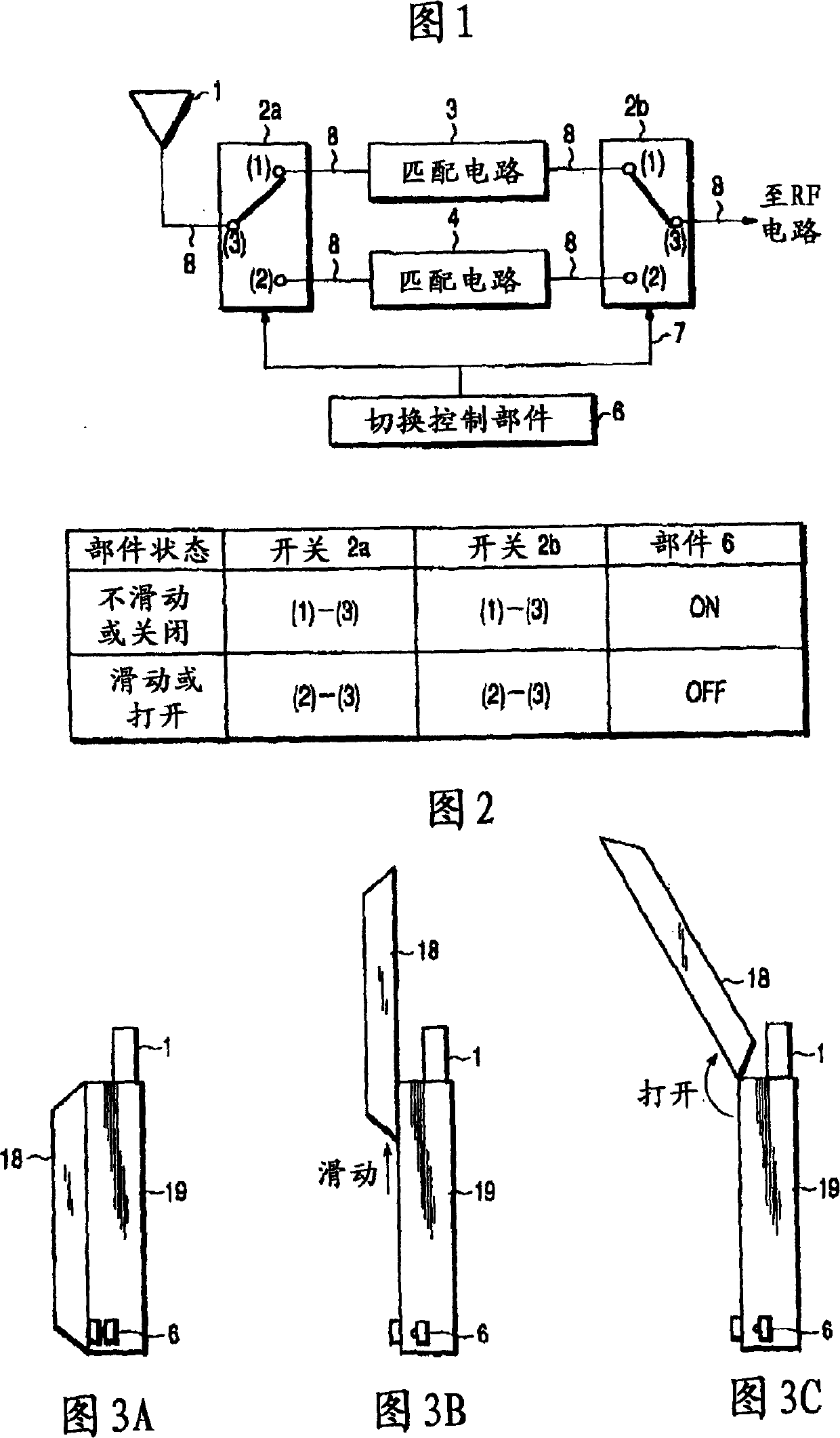
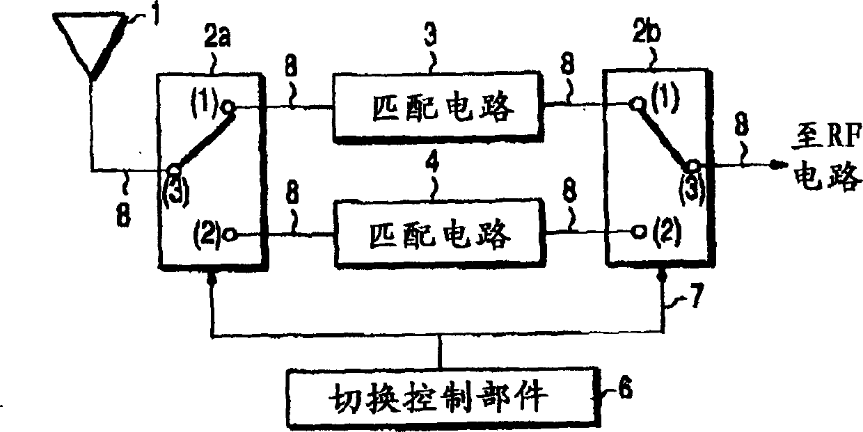
[0060] First, the basic principle of the embodiment of the present invention is explained.

[0061] The mobile radio device of the present invention including first and second components detects sliding / non-sliding or on / off status of components relative to each other, and changes constant or matching components such as matching circuits used between antennas and other circuits.

[0062] In such mobile radios, the best match can be used to detect slide / non-slide or open / closed states and avoid antenna gain drop due to mismatch.

[0063] The mobile radio device of the present invention can also optimize the sliding / non-sliding or open / closed state of matching parts with the extension and contraction of the antenna, and avoid the decrease of the antenna gain due to the mismatch.

[0064] Preferred embodiments of the present invention are described below with reference to the accompanying drawings.

[0065] (first embodiment)

[0066] FIG. 1 is a block diagram showing the confi...


PUM


Abstract

In a mobile radio apparatus, a matching circuit is selected to meet the detected condition detected by a switching control unit. Matching of the antenna to the RF circuit can be optimized and the antenna gain deterioration can be prevented.

Description

[0001] This application is based on and claims priority from prior Japanese Patent Application No. 2001-355101 filed on November 20, 2001, the entire contents of which are hereby incorporated by reference. technical field [0002] The present invention relates to mobile radio devices. Background technique [0003] Mobile radios having first and second components are known. In conventional mobile radios of this type, when either the first part 118 and the second part 119 are slid relative to each other as shown in FIGS. In the circuit, a matching circuit 130 as shown in FIG. 17 or a set of constants (values ​​realized by impedance matching units 131-133, coil L or capacitor C) as shown in FIG. 18 have been used for matching. [0004] In such a conventional mobile radio device, when it is assumed that these parts do not slide or close to match the antenna 101 with other circuits (for example, a radio frequency circuit) (refer to the graph of FIG. For other circuits, the ante...

Claims


Application Information

Patent Timeline
Patent Type & Authority Applications(China)
IPC IPC(8): H01Q3/24H01Q1/08H01Q1/24H01Q1/50H03H7/38H04B1/04H04B1/18H04B1/3822H04B1/40H04M1/00H04M1/725
CPCH04B1/18H04B1/0458
Inventor 渡边浩
Owner KK TOSHIBA
Why Eureka
Try Eureka