Air conditioner and its liquid storage device and method for producing liquid storage device

A technology of liquid accumulator and container, applied in the field of oil return functional components, can solve the problems of large pressure loss, high production cost, no refrigeration capacity, etc.

Inactive Publication Date: 2003-06-25
MITSUBISHI ELECTRIC CORP
View PDF0 Cites 13 Cited by
  • Summary
  • Abstract
  • Description
  • Claims
  • Application Information

AI Technical Summary

Problems solved by technology

Therefore, the pressure loss between the evaporator 5 and the compressor 1 is large, and there is not enough cooling capacity
The first liquid reservoir 6, the second liquid reservoir 7 and the connecting pipe 8 take up a relatively large space, and also need a longer connecting pipe 8 and two pressure vessels, so the production cost is higher
In addition, there will be a large number of solder points, which will reduce the reliability

Method used


Image

  • Air conditioner and its liquid storage device and method for producing liquid storage device
  • Air conditioner and its liquid storage device and method for producing liquid storage device
  • Air conditioner and its liquid storage device and method for producing liquid storage device

Examples


Embodiment 1

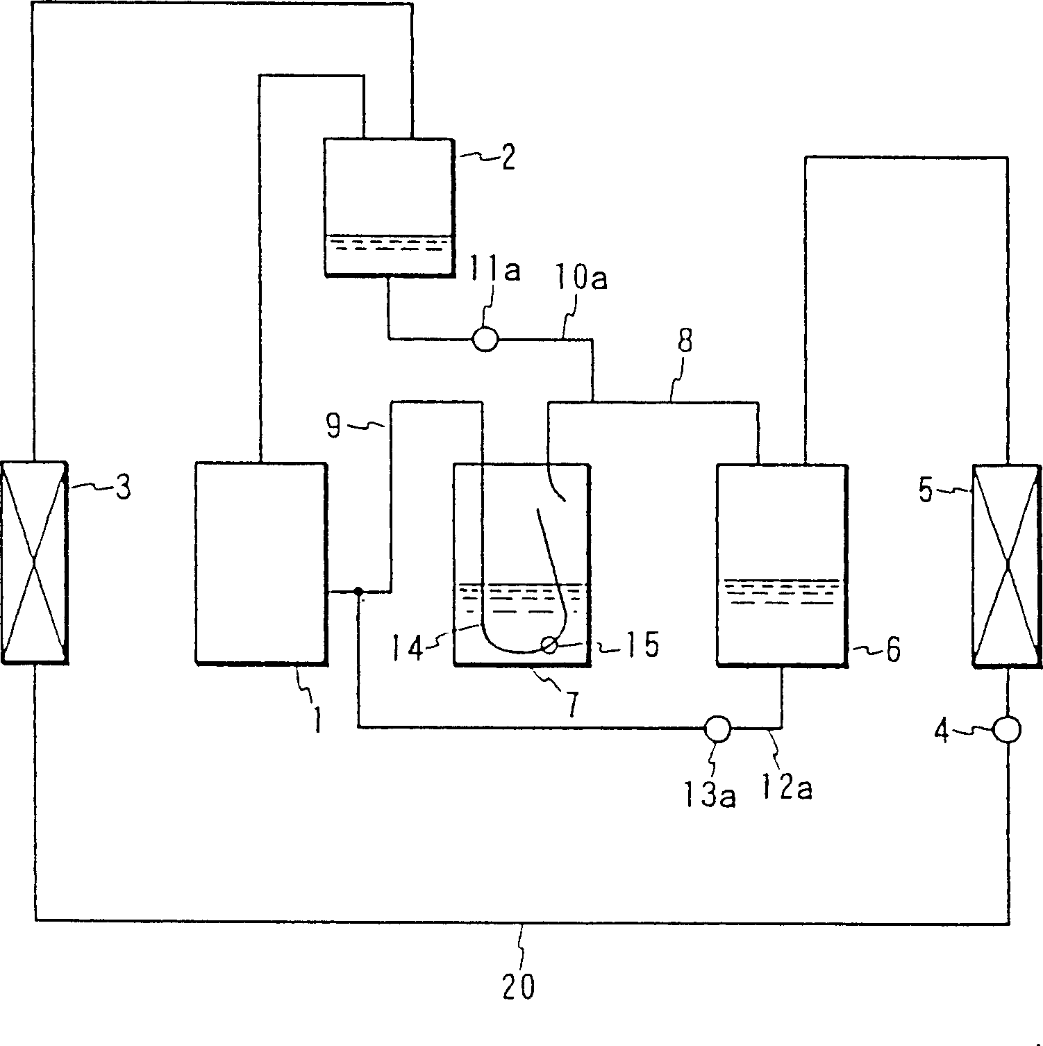
[0075] figure 1 It is the refrigerant circuit of the air conditioning system in the first embodiment of the present invention. In the drawing, numbers 1 to 9, 14 and 15 are associated with Figure 41 The refrigerant circuits shown are numbered for corresponding parts that are the same or similar and therefore will not be discussed here. The number 10a is the first oil return bypass connecting the oil separator 2 and the connecting pipe 8, and the number 11a is the first oil return device arranged at the midpoint of the pipeline of the first oil return bypass. The reference number 12a is the second oil return bypass connecting the bottom of the first liquid reservoir 6 and the connecting pipe 9, and the reference number 13a is the second oil return device arranged at the midpoint of the pipeline of the second oil return bypass 12a.

[0076] The flow process of refrigerant and lubricating oil is the same as that of the refrigerant circuit of a conventional air-conditioning sys...

Embodiment 2

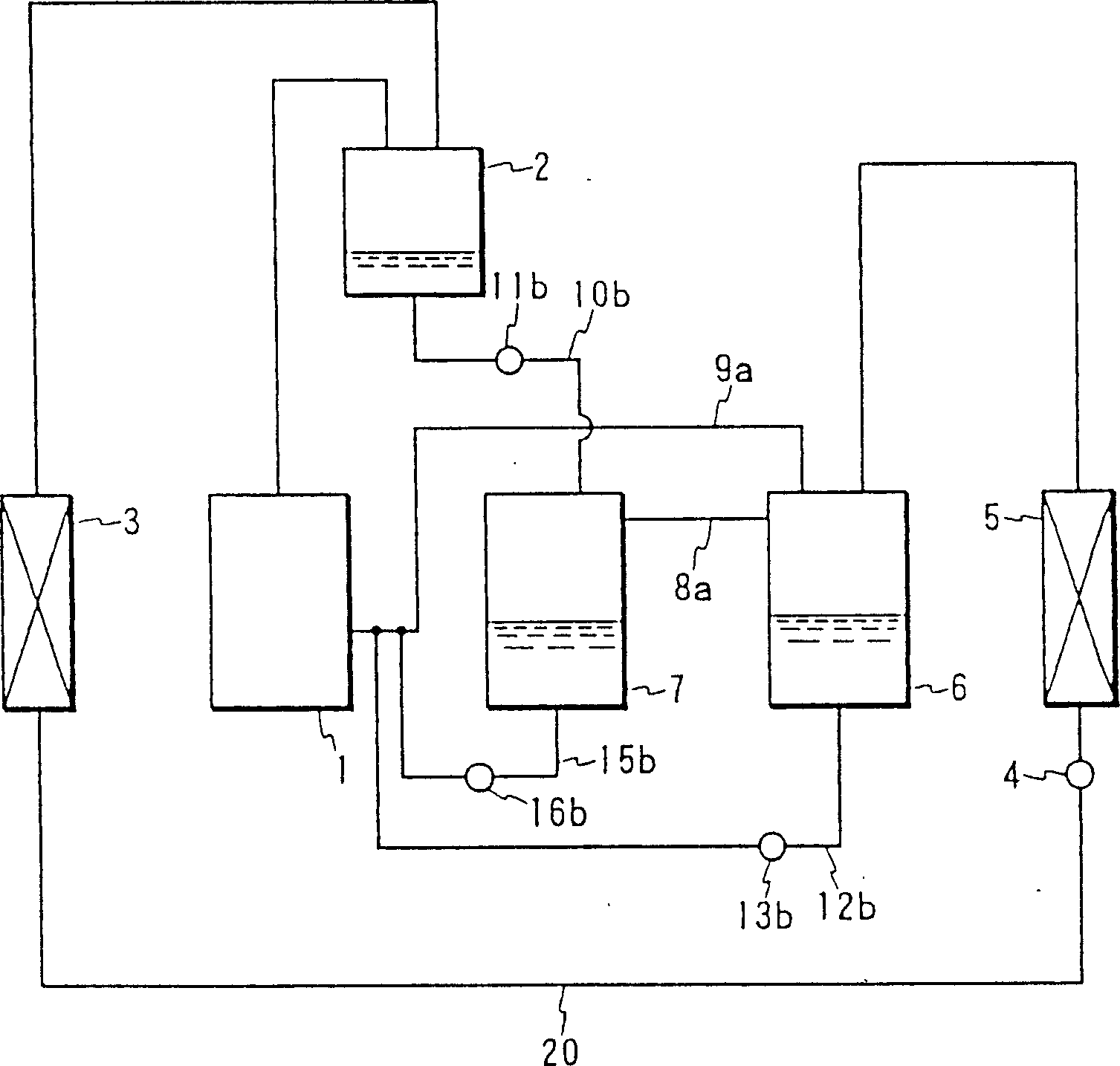
[0083] figure 2 It is the refrigerant circuit flow diagram of the air conditioning system according to the second embodiment of the present invention. In this figure, numbers 1 through 7 are associated with figure 1 The parts corresponding to the reference numerals of the refrigerant circuit of the air-conditioning system in the first embodiment shown are the same or similar, so no further discussion will be made here. The symbol 8a is a connecting pipe connecting the side top of the first liquid reservoir 6 and the side top of the second liquid reservoir 7, the symbol 9a is a connecting pipe connecting the first liquid reservoir 6 and the compressor 1, and the symbol 10b is The third oil return bypass connecting the oil separator 2 and the second liquid reservoir 7, the symbol 11b is the third oil return device arranged at the midpoint of the pipeline of the third oil return bypass 10b, and the symbol 15b is connected to the second oil return bypass. The bottom of the liqui...

Embodiment 3

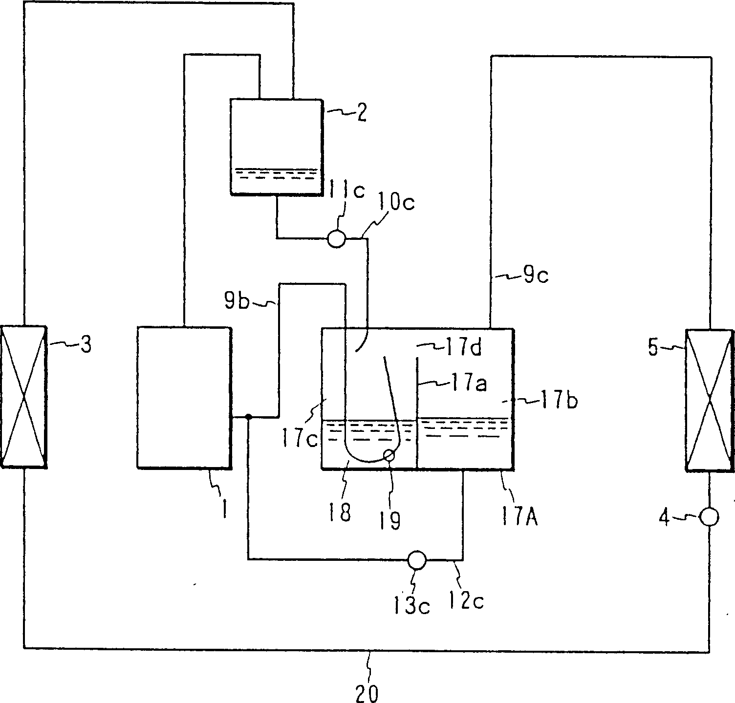
[0089] image 3 It is the refrigerant circuit flow diagram of the air conditioning system according to the third embodiment of the present invention. In this figure, numbers 1 to 5 are associated with figure 1 The parts corresponding to the reference numerals of the refrigerant circuit of the air-conditioning system in the first embodiment shown are the same or similar, so no further discussion will be made here. Symbol 17A is a liquid reservoir, symbol 9b is a connecting pipe that flows out of the liquid reservoir 17A and flows into the compressor 1, symbol 9c is an inflow pipe that flows from the indoor heat exchanger 5 into the liquid reservoir 17A, and symbol 17a is used to transfer the reservoir The interior of the liquid container 17A is divided into two cavities by a partition, the symbol 17b is the first chamber of the liquid reservoir 17A separated by the partition 17a; the label 17c is the second cavity of the liquid reservoir 17A separated by the partition 17a , ...


PUM


Abstract

An accumulator used with a refrigerant circuit is disclosed in the invention. The refrigerant circuit including a compressor, an oil separator, a condenser, a expansion device, an evaporator, and an accumulator connected in order by piping, a partition plate provided in a vessel of said accumulator to separate said vessel into first and second chambers; a communication hole provided at a top of said partition plate; a refrigerant inflow pipe disposed in said first chamber; a refrigerant effluent pipe disposed in at least one of said first and second chambers; and an oil effluent pipe and an oil inflow pipe which are disposed in said second chamber. The invention also discloses a method for manufacturing the accumulator.

Description

technical field [0001] The invention relates to an oil return functional element of an air-conditioning system, which includes a compressor, an oil separator, a condenser, an expansion valve, an evaporator and some liquid accumulators connected to each other through pipelines, It also relates to a liquid receiver for use in a refrigeration cycle and a method of manufacturing such a liquid receiver. Background technique [0002] Figure 41 Indicates a refrigerant circuit of a traditional air-conditioning system, where 1 is a compressor, 2 is an oil separator, 3 is a heat source machine heat exchanger used as a condenser when in use, 4 is an expansion device, and 5 is used as an evaporator when in use 6 is the first liquid reservoir, 7 is the second liquid reservoir, 8 is the connecting pipe used to connect the first and second liquid reservoirs 6 and 7, and 9 is used to connect the second liquid reservoir The connecting pipe between the liquid reservoir 7 and the compressor ...

Claims


Application Information

Patent Timeline
Patent Type & Authority Applications(China)
IPC IPC(8): F25B31/00F25B43/02
CPCF25B43/02F25B31/004
Inventor 仓地光教杉野雅彦河西智彦高下博文小野达生森安雅治久森洋一川口宪治藤原通雄
Owner MITSUBISHI ELECTRIC CORP
Why Eureka
Try Eureka