Control and monitoring signal transmission system

A technology for monitoring signals and transmission systems, applied in signal transmission systems, electrical signal transmission systems, general control systems, etc., and can solve problems such as limiting average power

Inactive Publication Date: 2003-07-09
ANYWIRE
View PDF0 Cites 12 Cited by
  • Summary
  • Abstract
  • Description
  • Claims
  • Application Information

AI Technical Summary

Problems solved by technology

Therefore, limiting the average power transmitted on the common data line

Method used


Image

  • Control and monitoring signal transmission system
  • Control and monitoring signal transmission system
  • Control and monitoring signal transmission system

Examples


Embodiment Construction

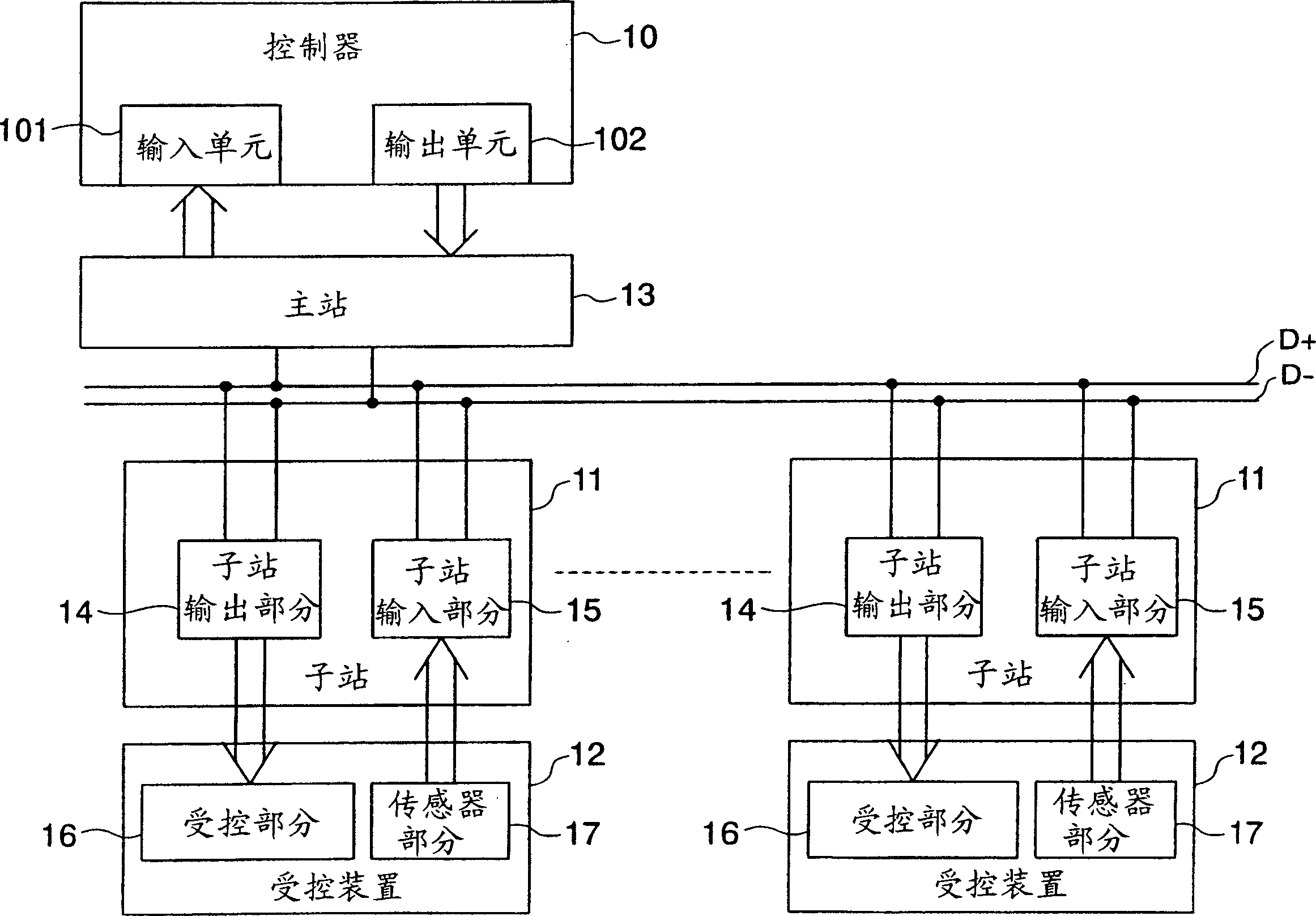
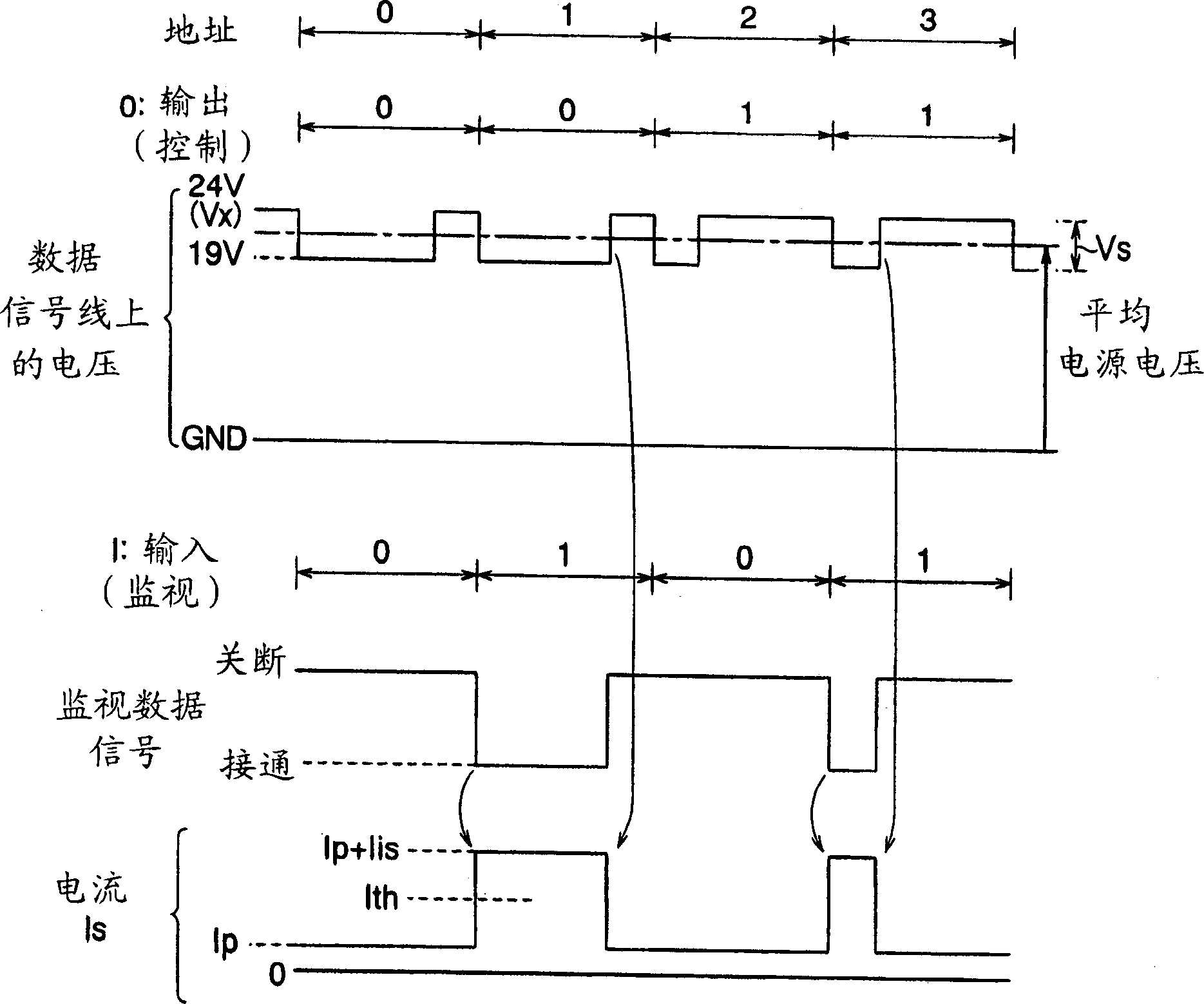
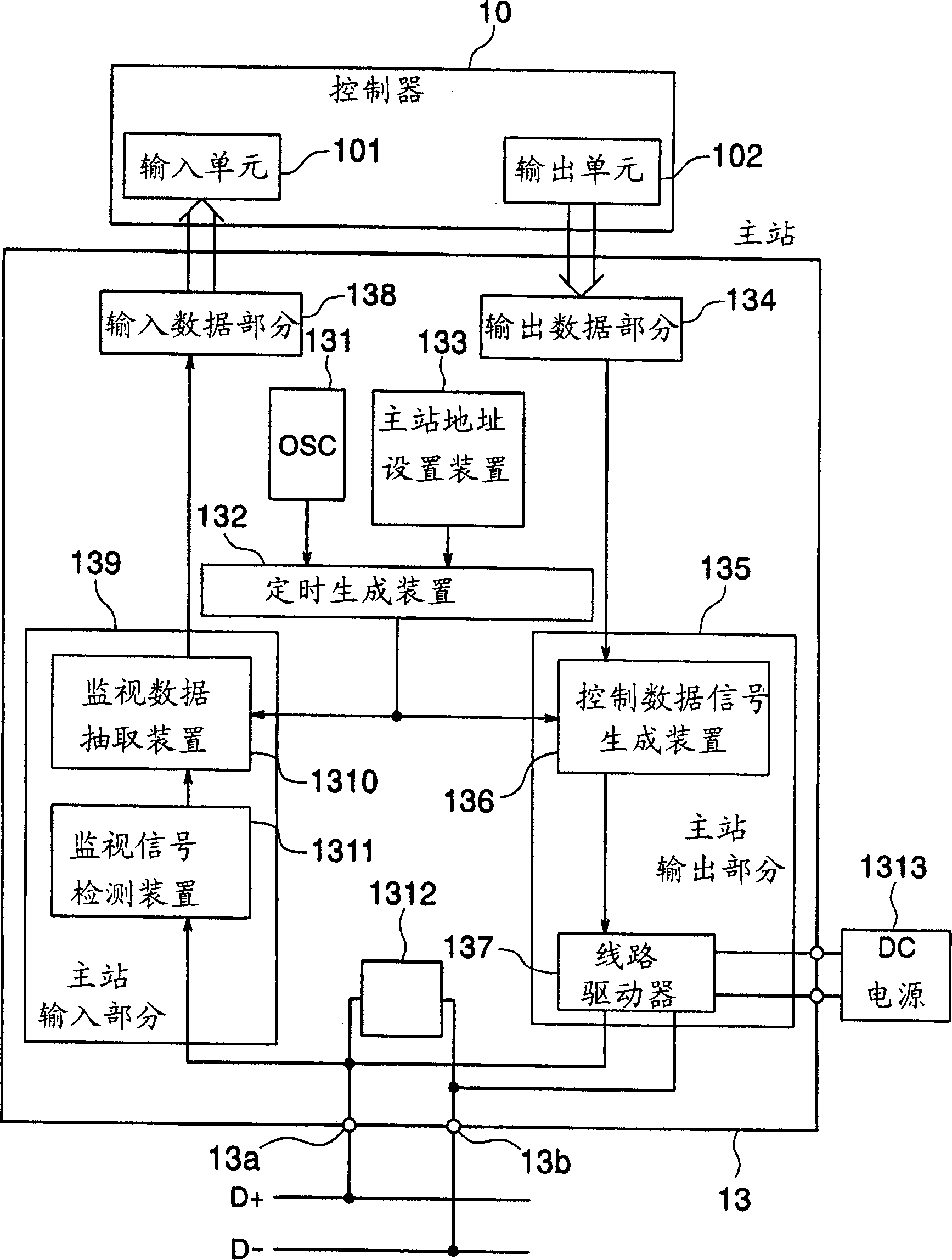
[0024] figure 1 , 3 and 4 represent the basic structure according to the invention. figure 2 Shows a diagram depicting signal transmission according to the present invention. Specifically, figure 1 Represents the structure of a control and monitoring signal transmission system of the present invention, image 3 represents the structure of the master station in the system, and Figure 4 Indicates the structure of substations in the system.

[0025] Such as figure 1 As shown, the control and monitoring signal transmission system includes a controller 10 and a plurality of controlled devices 12 , and each controlled device includes a controlled part 16 and a sensor part 17 for monitoring the controlled part 16 . The controller 10 can be a sequence controller, a programmable controller, a computer and the like. This controlled section 16 and sensor section 17 are referred to as a controlled device 12 . The controlled part 16 can be any element constituting the controlled ...


PUM


Abstract

A parent station output section changes a duty factor between a period in which a control data signal is at a level (high-potential low-level) lower than a power supply voltage Vx but higher than high-level signal in other circuit portions and a subsequent period in which the control data signal is at the power supply voltage Vx level to convert the control data signal into a serial pulse voltage signal and output the voltage signal onto data signal lines D+ and D- in accordance with each data value in the control data signal inputted from a controller in each cycle of a clock.

Description

technical field [0001] The present invention relates to a control and monitoring signal transmission system, and more particularly, to a control and monitoring signal transmission system in which parallel control signals from a controller are converted into serial signals and the serial signals are transmitted to remote device and serial-parallel conversion in the controlled device to drive the device, serial-parallel conversion of the monitoring signal of the sensor section for detecting the state of the device and providing to the controller, and superimposing the control signal on the clock signal, A power supply signal is also superimposed on this clock signal, and these monitor signals are superimposed on these signals. Background technique [0002] In the field of automatic control, a technique is widely used in which a control signal is transmitted from a controller such as a sequence controller, a programmable controller, or a computer to a plurality of remotely cont...

Claims


Application Information

Patent Timeline
Patent Type & Authority Applications(China)
IPC IPC(8): G05B15/02G05B19/042H03K19/0175H04B3/50H04L12/40H04L25/02H04Q9/00
CPCG05B19/042G05B2219/25188G05B2219/25028G05B2219/25132H04B3/50G05B19/05
Inventor 斋藤善胤锦户宪治汤川浩司森安
Owner ANYWIRE
Why Eureka
Try Eureka