Holding/sealing material for use in catalytic converter for clarifying gaseous emission

A technology for purifying exhaust gas and sealing materials, applied in catalyst protection, physical/chemical process catalysts, chemical instruments and methods, etc., can solve problems such as the deterioration of the working environment, and achieve the effect of a good working environment

Inactive Publication Date: 2003-08-20
IBIDEN CO LTD
View PDF0 Cites 18 Cited by
  • Summary
  • Abstract
  • Description
  • Claims
  • Application Information

AI Technical Summary

Problems solved by technology

Therefore, it may lead to the deterioration of the working environment in the work area where the above-mentioned assembly operation is performed. When performing the above-mentioned assembly operation, for example, workers must wear dust masks to perform operations.

Method used


Image

  • Holding/sealing material for use in catalytic converter for clarifying gaseous emission
  • Holding/sealing material for use in catalytic converter for clarifying gaseous emission
  • Holding/sealing material for use in catalytic converter for clarifying gaseous emission

Examples


Embodiment 1

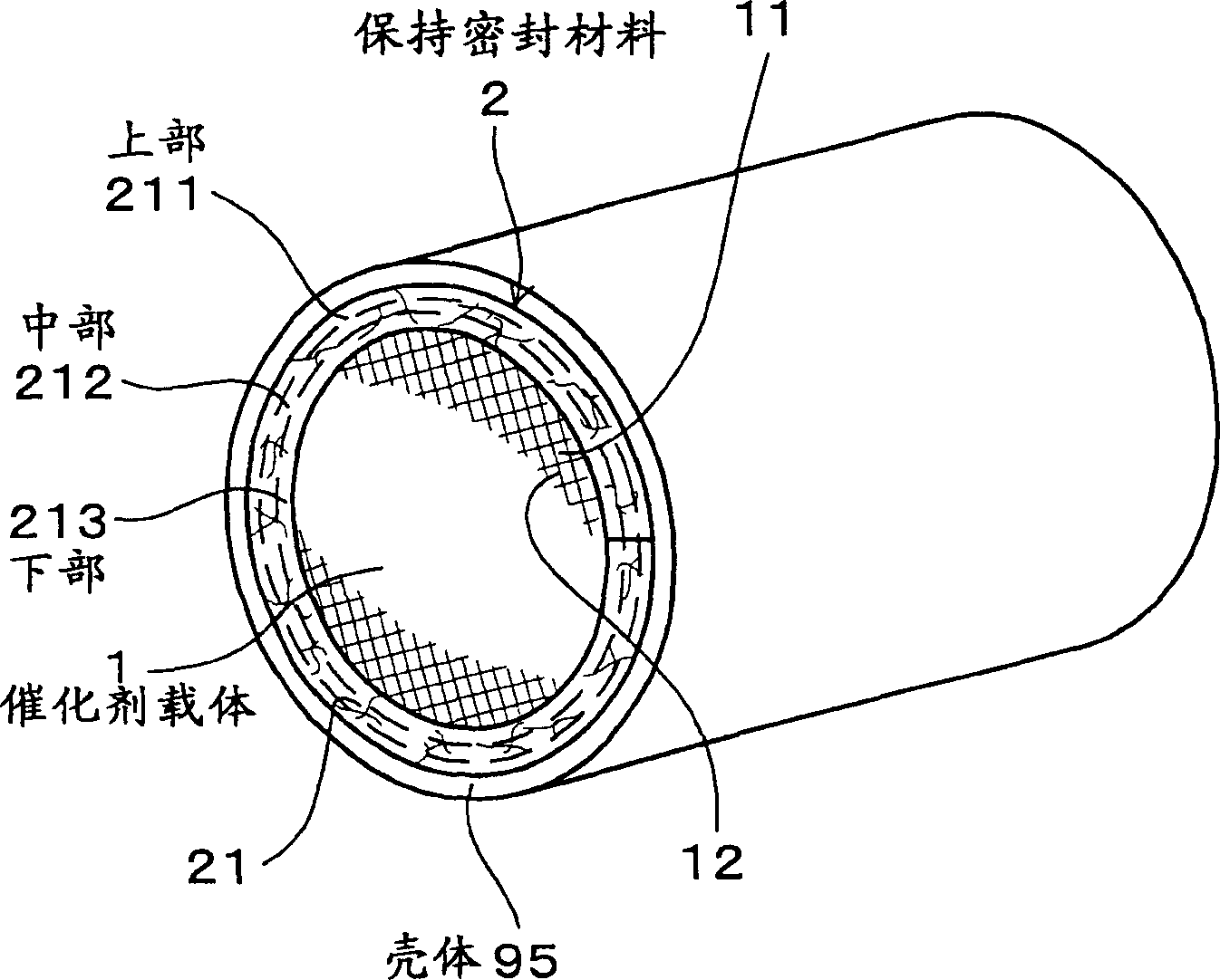
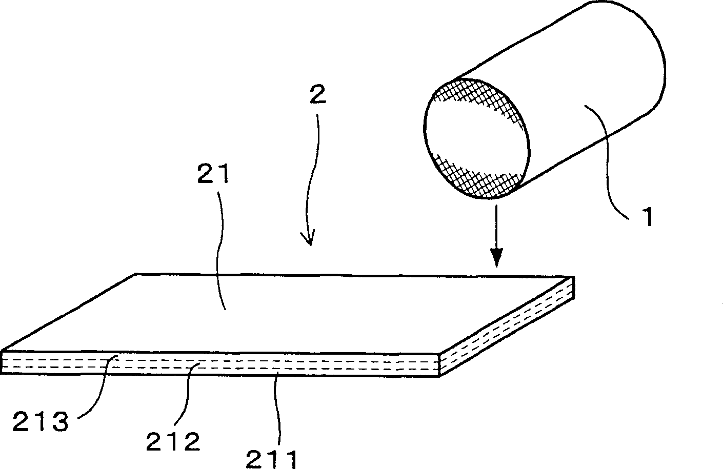
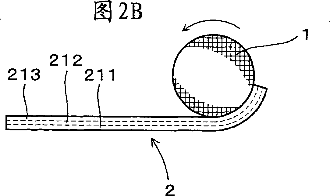
[0032] use Figure 1 to Figure 5 The holding sealing material of the catalytic converter for purifying exhaust gas in the embodiment of the present invention will be described.

[0033] Such as figure 1 As shown, the holding sealing material 2 in this embodiment is used by being placed between the catalyst carrier 1 and the case 95 covering the outer side of the exhaust gas-purifying catalytic converter 10 . In addition, the binder that will be made of 0.5~20% by weight of organic binder or inorganic binder is added to the cushion material 21 (referring to Fig. 2 (A), Figure 2(B)) to form a holding sealing material 2, and at the same time, adjust the packing density after assembly to 0.1 ~ 0.6g / cm 3 In the range.

[0034] And, in the above-mentioned holding sealing material 2: the upper part 211, the middle part 212, and the lower part 213 are divided into three equal parts along the thickness direction of the above-mentioned cushion-shaped material 21 to measure the solid...

Embodiment 2

[0053] In this example, the following drop test was performed in order to ensure that the inorganic fibers contained in the mat-like material 21 were not easily scattered into the air.

[0054] That is, in this drop test, cushion-like materials 21 (invention products 1 and 2) to which different binders were added and cushion-like materials 21 (comparative products) to which no binder was added were used. Fall from height 10 times. Afterwards, by detecting the weight loss rate of the mat-like material 21 after falling, the scattering of the inorganic fibers in the mat-like material 21 into the air can be measured.

[0055] (Invention product 1)

[0056] In the free state before assembly, with a bulk density of 0.05g / cm 3 1. In the cushion-like material 21 made of crystalline aluminum fibers with a thickness of 25 mm, latex was added as a binder to account for 1% (percentage by weight) of the cushion-like material 21 as a whole. In addition, the distribution rate of the adhes...


PUM

PropertyMeasurementUnit
densityaaaaaaaaaa
thicknessaaaaaaaaaa

Abstract

An object of the invention is to provide a holding and sealing mat material of a catalytic converter for purifying an exhaust gas which can prevent inorganic fibers from flying in all directions from a surface of the holding and sealing mat material, and can keep a working environment at a time of assembling good. In the holding and sealing mat material of a catalytic converter for purifying an exhaust gas, which is arranged between a catalyst carrier and a shell covering the catalyst carrier from the outside thereof, the holding and sealing mat material includes a mat-like material consisting of inorganic fibers and being formed in a mat shape and a binder of 0.5 to 20 weight % of an organic binder or an inorganic binder, which is attached to the mat-like material, wherein a filling bulk density of the holding and sealing mat material after being assembled is within a range between 0.1 and 0.6 g / cm<3>, and wherein in the case of estimating distribution rates of solids constituents in the binder attached to the mat-like material by dividing the mat-like material into three equal parts of an upper portion, a middle portion and a lower portion in a thickness direction, the distribution rates of the upper portion and the lower portion are higher than that of the middle portion.

Description

technical field [0001] The present invention relates to a catalytic converter for purifying exhaust gas for purifying exhaust gas discharged from an internal combustion engine, and more particularly to a holding sealing material thereof. Background technique [0002] Such as Image 6 As shown, conventionally, in order to purify exhaust gas discharged from an engine 92 such as an internal combustion engine, a catalytic converter 90 for purifying exhaust gas is used. The catalytic converter 90 for purifying exhaust gas has a catalyst carrier 1 , a metal material case 95 covering the outer side thereof, and a holding sealing material 91 provided therebetween. The holding sealing material 91 can prevent leakage of gas discharged from between the catalyst carrier 1 and the metal material casing 95 , and can prevent the catalyst carrier 1 from being damaged due to contact with the metal material casing 95 . [0003] In addition, when manufacturing the above-mentioned exhaust gas-...

Claims


Application Information

Patent Timeline
Patent Type & Authority Applications(China)
IPC IPC(8): B01D53/86B01D53/94B01J33/00C04B30/02F01N3/28
CPCF01N3/2853C04B2111/00405C04B30/02B01D53/9454C04B2111/0081Y02T10/22Y02T10/12Y10T29/49345Y10T428/24058Y10T428/24124Y10T428/25Y10T428/27Y10T428/2913Y10T428/23921Y10T428/249967Y10T428/249989C04B14/46B01D53/86
Inventor 安形政直
Owner IBIDEN CO LTD
Why Eureka
Try Eureka