Holding device for treated body

A technology for objects to be processed and holding devices, which is applied to holding devices, positioning devices, and electric solid devices using electrostatic attraction, and can solve problems such as increased costs and complex structures

Inactive Publication Date: 2003-08-20
TOKYO ELECTRON LTD
View PDF2 Cites 11 Cited by
  • Summary
  • Abstract
  • Description
  • Claims
  • Application Information

AI Technical Summary

Problems solved by technology

However, this mechanical device has a complex structure due to the engaging and disengaging connectio

Method used


Image

  • Holding device for treated body
  • Holding device for treated body
  • Holding device for treated body

Examples


Embodiment Construction

[0023] Hereinafter, embodiments of the present invention will be described in detail with reference to the drawings.

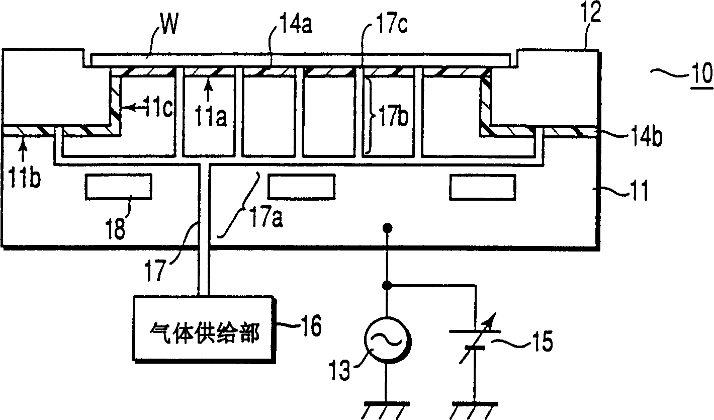
[0024] figure 1 It is a cross-sectional view of a configuration example of the object holding device according to the first embodiment of the present invention.

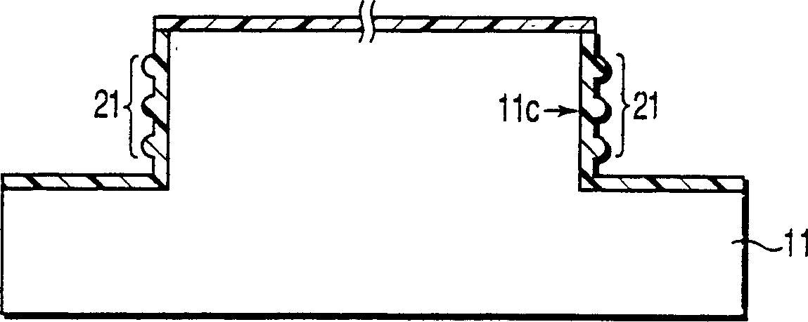
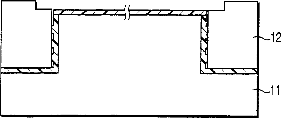
[0025] The object holding device 10 is composed of a convex base body 1 , a first dielectric film 14 a , a second dielectric film 14 b and a focus ring 12 . A semiconductor wafer (hereinafter referred to as a wafer) W as an object to be processed is transported and placed on the susceptor body 1 by a transport device not shown in the figure. The first dielectric film 14 a covers the wafer mounting surface (holding portion) 11 a on the boss surface of the susceptor body 1 . The second dielectric film 14b covers the focus ring mounting surface (flange) 11b of the boss outer peripheral edge portion of the base body 1 and the side wall surface 11c of the boss. The focus ring 12 then engages in the fla...


PUM


Abstract

The holding device for an object to be processed of the present invention has: a base body, a first dielectric film, and a second dielectric film. The susceptor body is in the shape of a boss, and is composed of a holding portion which is placed in the plasma processing apparatus and holds the placed object to be processed, and a flange provided on the outer peripheral edge of the holding portion for fitting the focus ring. The first dielectric film adsorbs the object to be processed placed on the holding portion to the susceptor body by Coulomb force. The second dielectric film adsorbs the focus ring placed on the flange to the base body by virtue of the Johnson-Rabeck force, which is stronger than that of the first dielectric film. The device increases the electrostatic adsorption force of the focus ring on the base body, improves the cooling effect, and the plasma processing characteristics near the focus ring will not change with time, and can uniformly process the entire object to be processed.

Description

technical field [0001] The present invention relates to a processing target holding device which is placed in a processing chamber of a plasma processing device or the like to hold a processed object. Background technique [0002] Generally, as an apparatus for performing plasma processing on a substrate to be processed such as a semiconductor wafer, a CVD apparatus, an etching apparatus, etc., an ashing apparatus for removing a resist mask, etc. are well known. [0003] This plasma processing apparatus has a processing chamber for generating plasma in an atmosphere in which a processing gas is introduced, and processing a loaded substrate to be processed. In the processing chamber (processing chamber), a device for generating plasma The electrode function and the holding device for holding the object to be treated. [0004] FIG. 5 shows a configuration example of a conventional holding device. [0005] The holding device consists of a mounting table (base body) 1 on which...

Claims


Application Information

Patent Timeline
IPC IPC(8): B23Q3/15C23C16/458H01L21/205H01L21/302H01L21/3065H01L21/60H01L21/68H01L21/683H02N13/00
CPCH01L21/6835H01L2924/01033H01L2924/01023H01L2924/01074H01L2924/01082H01L24/90H01L21/6831H01L2924/01078H01L2924/01004H01L2924/01013H01L21/6833C23C16/4585
Inventor 舆石公桧森慎司
Owner TOKYO ELECTRON LTD
Why Eureka
Try Eureka