Back light source and front light source and liquid crystal display device

A technology of a liquid crystal display device and a liquid crystal display unit, which is applied in the field of liquid crystal display devices with the backlight or front light source, can solve the problems of low luminance, large power consumption, and short light-emitting life of EL elements, and achieve cost reduction, less noise effect

Inactive Publication Date: 2003-09-10
ALPS ALPINE CO LTD
View PDF0 Cites 32 Cited by
  • Summary
  • Abstract
  • Description
  • Claims
  • Application Information

AI Technical Summary

Problems solved by technology

[0005] However, when an EL element is used as the light source of such a display machine, in order to obtain several Cd / m 2 About 4~5mW / cm of luminance needs to be consumed 2 There is a problem of high power consumption and low luminance
[0006] In addition, in the EL element, in order to make the element itself emit light, an inverter is required in the amplifier circuit, which will become a noise source for the liquid crystal display device
In the prior art, as noise countermeasures against the inverter, it is necessary to install a noise countermeasure circuit and a shielding device in the liquid crystal display device, which is a major cause of cost increase.
In addition, the above-mentioned inverter also has the disadvantage of high cost as a circuit itself
[0007] In addition, the EL element has the disadvantage of relatively short luminous life, and parts replacement and maintenance are required for long-term use.

Method used


Image

  • Back light source and front light source and liquid crystal display device
  • Back light source and front light source and liquid crystal display device
  • Back light source and front light source and liquid crystal display device

Examples


no. 1 Embodiment

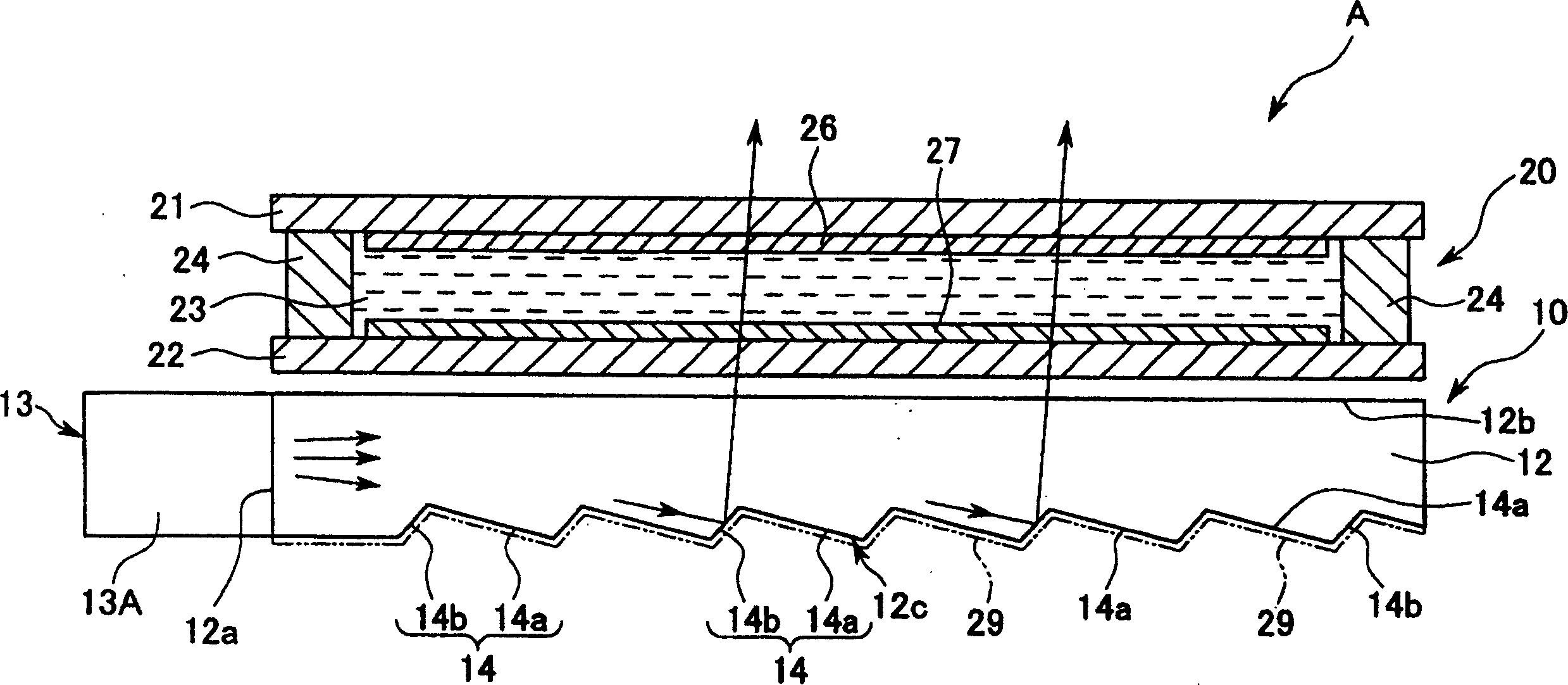
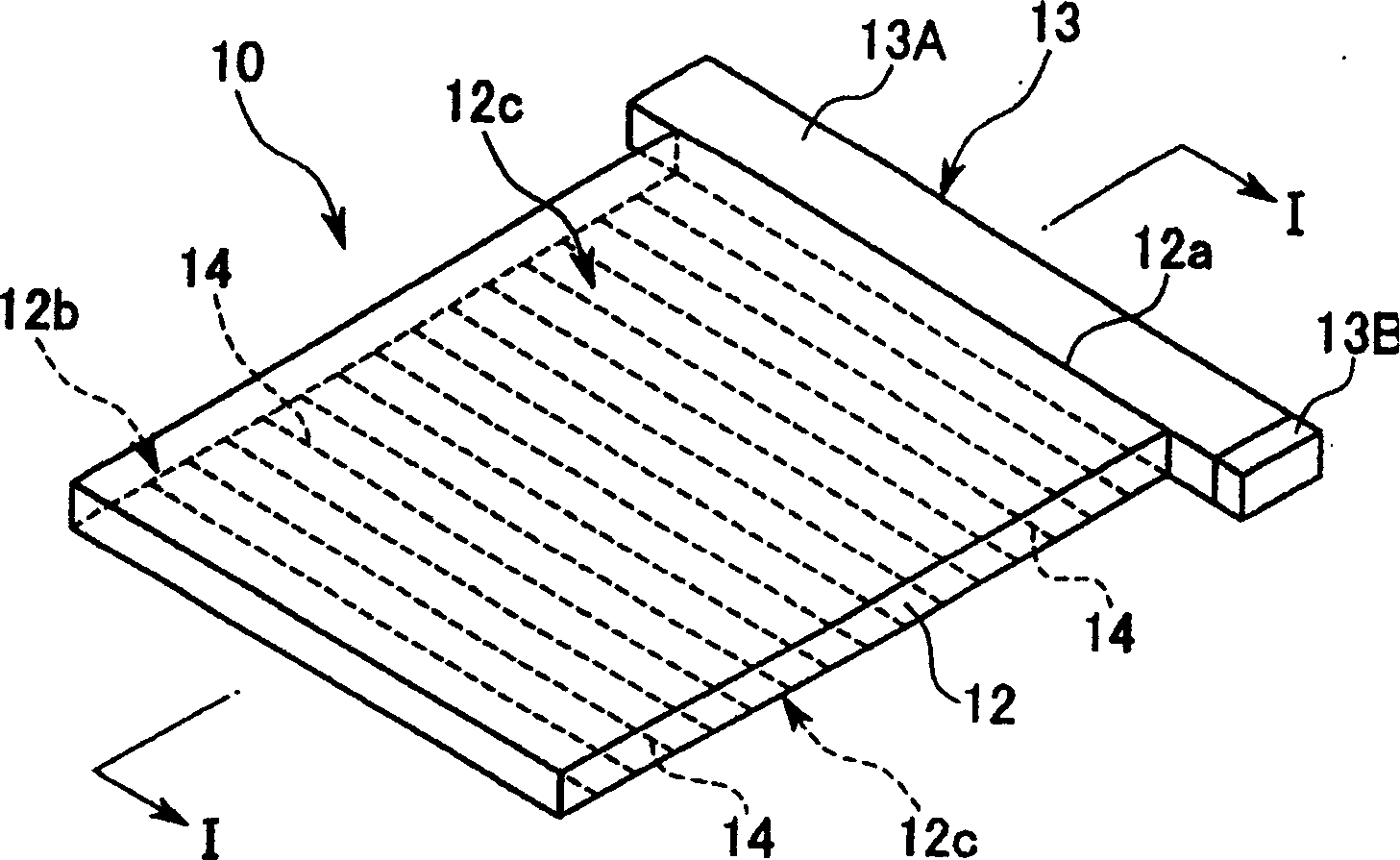
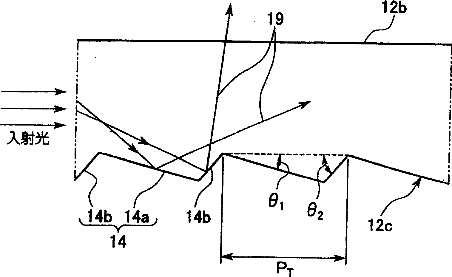
[0069] figure 1 A cross-sectional view showing a transmissive or semi-transmissive liquid crystal display device including a backlight (planar light-emitting device) according to the first embodiment of the present invention, figure 2 represents a perspective view of the backlight, image 3 A partially enlarged side view of the backlight is shown. figure 1 The cross-sectional direction is along the figure 2 The direction of the I-I line.

[0070] The liquid crystal display device A of this embodiment is roughly composed of a liquid crystal display unit 20 and a backlight 10 arranged on the back side of the liquid crystal display unit 20 to illuminate the liquid crystal display unit 20 from the back side.

[0071] The liquid crystal display unit 20 is a transmissive or semi-transmissive type in this embodiment, and is generally configured as a transparent first substrate 21 made of glass sandwiching a liquid crystal layer 23 and a transparent second substrate 22 with an ...

no. 2 Embodiment

[0104] Figure 10 A partial perspective view showing the configuration of a front light source (surface light emitting device) according to a second embodiment of the present invention. in addition, Figure 11 means from Figure 10 The shown front light source 50 is a partial perspective view of a state where a cover member 58 described later is removed. The front light source 50 shown in these figures includes a flat plate-shaped light guide plate 52 made of a transparent resin material, and a side end portion (one end on the short side of the rectangular light guide plate 52) disposed on the side end surface 52a side of the light guide plate 52. part), the rod-shaped light guide (light guide) 53 on the rod-shaped light guide 53, the light-emitting elements (light sources) 55, 55 arranged on both ends of the rod-shaped light guide 53 in the longitudinal direction, and the light-emitting elements covering the above-mentioned rod-shaped light guide 53 The element 55 and the ...


PUM

PropertyMeasurementUnit
lengthaaaaaaaaaa

Abstract

A backlight that has small power consumption and can display a high luminance and has a long life with little noise generation, and a liquid crystal display device. This is a backlight 10 that is installed on the back side of an illuminated object 20 and illuminates the illuminated object from the back side and comprises a light guide plate 12, an intermediate light guide body 13A that is arranged along one side end, and a light source 13B that is provided at the end part of the intermediate light guide body. One side of the light guide plate is made a reflecting face 12c that is formed of a concavo-convex shape for reflecting the light propagating inside and the other side of the light guide plate is made an exit face 12b for radiating the light reflected by the reflecting face. And a plurality of grooves 14 that are formed by a low slope part 14a and a steep slope part 14b are formed continuously on the reflecting face in stripe form and the illuminated object is provided at the outside of the exit face.

Description

technical field [0001] The invention relates to a backlight source or a front light source structure suitable for a liquid crystal display device, and a liquid crystal display device with the backlight source or front light source. Background technique [0002] Figure 20 A schematic cross-sectional view showing an example of a conventional transmissive liquid crystal display device. The liquid crystal display device 100 of this example is roughly composed of a liquid crystal display unit 120 and a backlight 110 disposed on the rear side of the liquid crystal display unit 120 . [0003] The structure of the backlight 110 is such that the light emitted by the rod-shaped light source 113 enters the light guide plate 112 from one end surface (incident surface 112a) of the light guide plate 112, and makes it pass through the light guide plate 112 from the side facing the liquid crystal cell 120. (Emitting surface 112b) is emitted. A prism sheet 114 and a white sheet 115 are seq...

Claims


Application Information

Patent Timeline
Patent Type & Authority Applications(China)
IPC IPC(8): G02B6/00F21V8/00F21Y101/02G02F1/13357
CPCG02B6/0018G02B6/0038G02B6/0028G02B6/0016G02F1/1335
Inventor 鹿野满
Owner ALPS ALPINE CO LTD
Why Eureka
Try Eureka