Rotor assembly for electric motor and electric motor with internal rotor

A technology of electric motors and inner rotors, which is applied in the field of brushless motors and DC motors, can solve the problems of unsuitable and not allowing direct mechanical connection of loads, etc., and achieve the best effect of utilization

Inactive Publication Date: 2003-09-10
MINEBEA CO LTD
View PDF2 Cites 5 Cited by
  • Summary
  • Abstract
  • Description
  • Claims
  • Application Information

AI Technical Summary

Problems solved by technology

However, for the transmission of large torques, such as are required for motor vehicles, they are completely unsuitable
[0009] Secondly, the inner rotor motor of DE3237196 has the disadvantage that the hermetically sealed package of the rotor assembly does not allow a direct mechanical coupling of the load, but rather the torque transmission from the rotor to the shaft has to be realized only in an indirect manner, for example by means of a magnetic coupling Shafter, as described in the patent specification

Method used


Image

  • Rotor assembly for electric motor and electric motor with internal rotor
  • Rotor assembly for electric motor and electric motor with internal rotor
  • Rotor assembly for electric motor and electric motor with internal rotor

Examples


Embodiment Construction

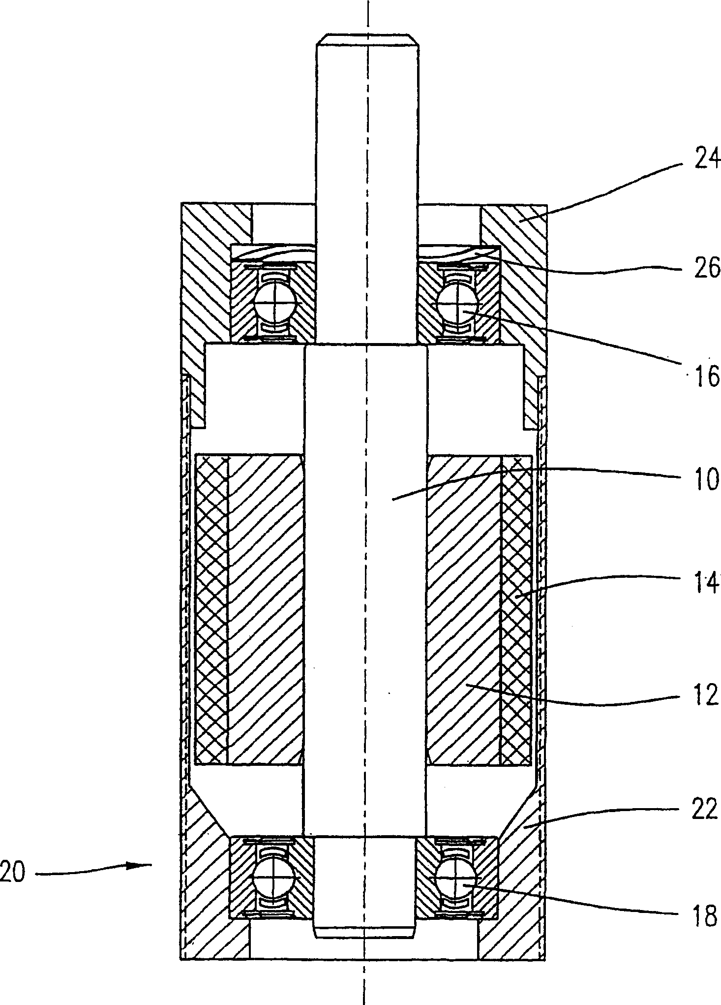
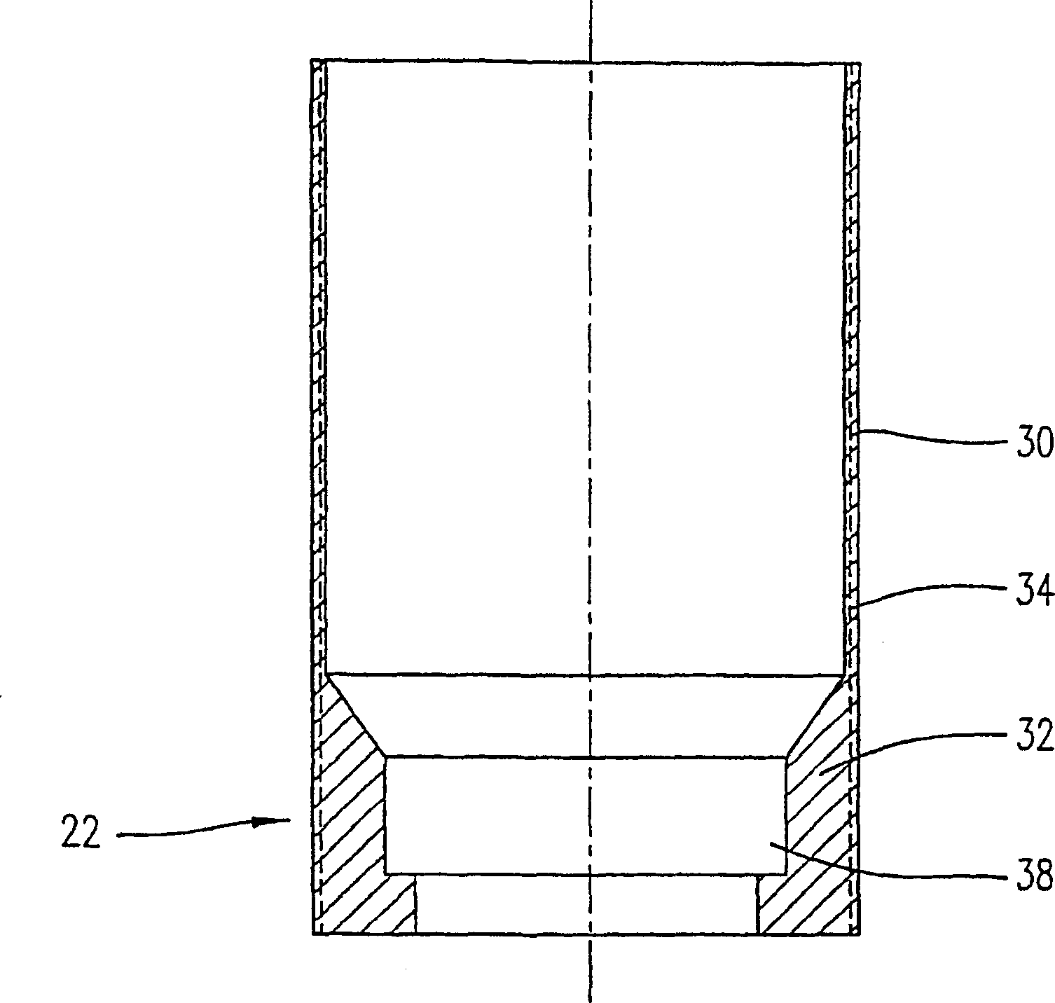
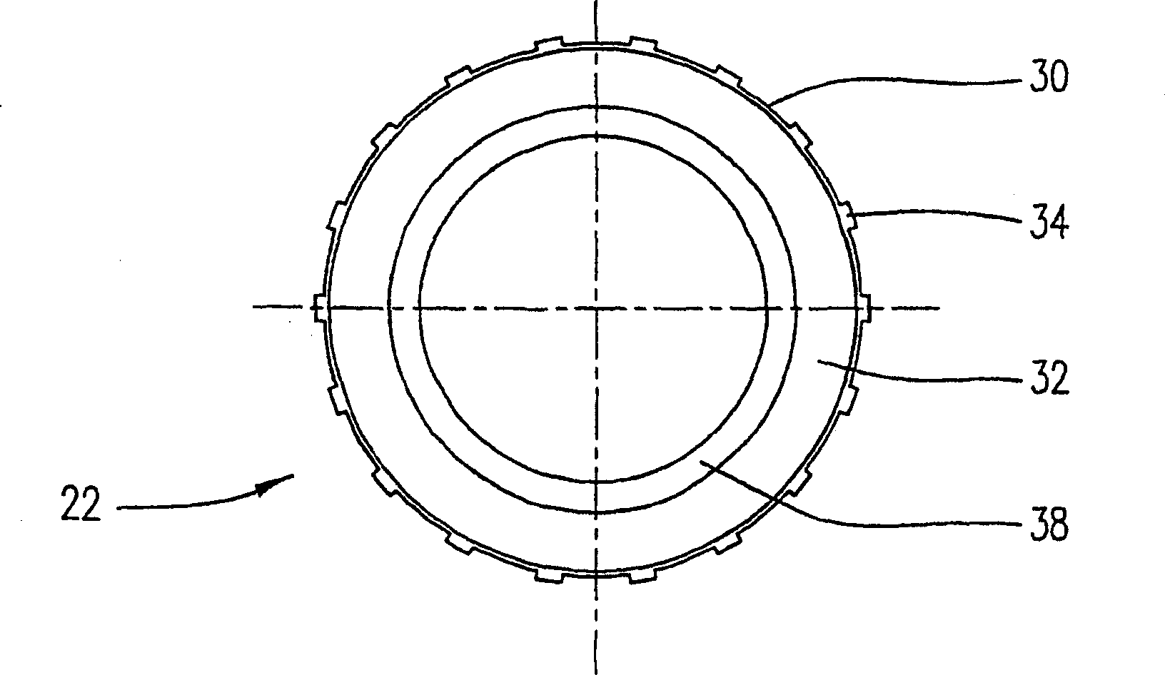
[0035] figure 1 A cross-sectional view of a preferred embodiment of a rotor assembly according to the invention is shown. The rotor assembly according to the invention comprises a rotor shaft 10 carrying a yoke ring 12 made of a soft magnetic material such as iron. Attached to the yoke ring 12 is a preferably annular permanent magnet 14 . The shaft 10 is rotatably journaled in bearings 16 , 18 , wherein the bearings 16 , 18 can be formed as anti-friction or friction bearings and in particular as roller bearings. Here the rotor, made of rotor shaft 10, yoke ring 12 and permanent magnets 14, is sealed in a sleeve 20 comprising a sealing section 22 and a flange section 24, which will be referred to Figures 2 to 5 Explain in detail.

[0036] The bearings 16, 18 can be preassembled on the rotor shaft 10 and placed in the end faces of the sleeve sections 22, 24, pressed into them and / or glued to them, or fixed in another suitable way . In the illustrated embodiment, an annular...


PUM


Abstract

An electric motor having a stator arranged on a sleeve; and a rotor assembly having a rotor shaft and at least one permanent magnet arranged on the rotor shaft, the rotor shaft being rotatbly housed in the sleeve. An external dimension of the rotor assembly and an internal dimension of the stator are selected such that the rotor assembly is free to move in the axial direction while the rotor assembly is inserted into the stator. The rotor assembly is aligned within the stator in the magnetic center of the stator by self-centering magnetic forces.

Description

technical field [0001] The present invention relates to a rotor assembly for an electric motor, which has a rotor shaft and at least one permanent magnet arranged on the rotor shaft; an inner rotor motor using such a rotor assembly; and a method for manufacturing such an inner rotor assembly. Rotor motor method. [0002] The invention relates to the field of brushless motors with permanent magnets, and in particular to the field of direct current motors designed as so-called inner rotor motors. An inner rotor motor includes a rotor assembly including a rotor shaft and one or more permanent magnets disposed on the rotor shaft, and the rotor assembly is inserted into a stator unit including a stator body and field windings. Background technique [0003] One construction of such a motor is described in US Patent No. 5,970,600. The electric motor includes a frame incorporating a stator, rotor assembly and bearings for rotatably journaling the rotor assembly. The stator includ...

Claims


Application Information

Patent Timeline
Patent Type & Authority Applications(China)
IPC IPC(8): H02K15/02H02K5/128H02K5/15H02K15/03H02K21/14
CPCH02K5/128H02K1/27
Inventor 哈拉尔德·拉普
Owner MINEBEA CO LTD
Why Eureka
Try Eureka