Mixed liquid blending system and blending method

A technology of mixing liquid and mixer, which is applied in mixers, chemical instruments and methods, mixer accessories, etc., can solve the problems of reduced tool life, the mixed liquid does not meet the requirements for use, and the concentration of the mixed liquid is unstable.

Inactive Publication Date: 2015-12-16
JIANGSU DONGRAN ELECTRONICS TECH CO LTD
View PDF5 Cites 0 Cited by
  • Summary
  • Abstract
  • Description
  • Claims
  • Application Information

AI Technical Summary

Problems solved by technology

Existing problems: high labor intensity, uneven mixing, inaccurate concentration in the metering scale, and large influence of human factors
[0004] 2. Semi-automatic allocation using Venturi tube: Although this allocation method improves work efficiency, due to some objective and realistic reasons, such as Figure 5 As shown, the concentration of its deployment fluctuates greatly, and the concentration gradually decreases with time. There is no repeatability, and the mixed solution prepared cannot meet the requirements for use.
[0005] Because the concentration of the prepared mixed solution is unstable, it cannot meet the requirements of production or life. For example, if the concentration of cutting fluid is not stable, it will cause corrosion of equipment or workpieces, and the surface finish of workpieces will be low. Problems such as decreased tool life or smelly solution

Method used


Image

  • Mixed liquid blending system and blending method
  • Mixed liquid blending system and blending method
  • Mixed liquid blending system and blending method

Examples


Embodiment 1

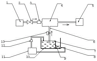
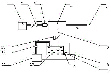
[0036] Adopt the technical scheme disclosed by the invention to deploy the cutting fluid mixture, such as figure 1 As shown, a blending system of a cutting fluid mixture includes a stock solution unit, a diluent unit, a mixer 4 and a central controller. The stock solution unit and the diluent unit are respectively connected to the mixer 4; the stock solution unit is provided with a liquid level sensor 7; A solenoid valve 2 is provided between the diluent unit and the mixer 4; a voltage regulator 3 is provided between the solenoid valve 2 and the mixer 4, and the solenoid valve 2 is electrically connected to the voltage regulator 3; the liquid level sensor 7 is connected to the central control by communication device; the central controller controls and connects the solenoid valve 2.

[0037] The stock solution unit comprises a stock solution pool 11 and a liquid supply pool 10. The stock solution in the stock solution pool 11 flows into the liquid supply pool 10 through a pum...

Embodiment 2

[0052] The rest is the same as that of Embodiment 1, except that the liquid level sensor is arranged on the side wall of the liquid supply tank, and the height of the liquid level sensor is slightly lower than the height of the baffle.

Embodiment 3

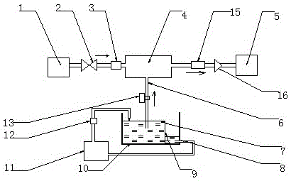
[0054] All the other are identical with embodiment 1, and difference is, as figure 2 As shown, the liquid level sensor is located at the bottom of the overflow port.

[0055] When the raw liquid in the overflow area is cut off, the liquid level sensor cannot detect the liquid level of the raw liquid, and sends a signal to the controller, the controller closes the solenoid valve, and the mixer is closed.


PUM


Abstract

A blending system for a mixed liquid, used for blending a mixed liquid and maintaining a stable concentration of the mixed liquid, comprising a stock solution unit, a diluent unit, a mixer and a central controller, the stock solution unit and the diluent unit are respectively connected to the mixer; the stock solution The unit is equipped with a liquid level sensor; a solenoid valve is installed between the diluent unit and the mixer; a voltage regulator is installed between the solenoid valve and the mixer; the solenoid valve is electrically connected to the voltage regulator; the liquid level sensor is connected to the central controller by communication ; The central controller controls the connecting solenoid valve. A mixed liquid blending system disclosed by the present invention is used to keep the concentration of the mixed liquid stable by keeping the liquid level of the original liquid and the pressure and flow rate of the diluent constant during operation. When the liquid level of the original liquid or the flow rate of the diluent changes, the system automatically Stop work to ensure that no unqualified mixed liquid enters the production system. The invention also relates to a blending method for blending liquid by using the blending system.

Description

technical field [0001] The invention relates to a mixed liquid blending device, in particular to a blending system for blending mixed liquid and maintaining a stable concentration of the mixed liquid and a blending method using the blending system to configure the mixed liquid. Background technique [0002] The deployment of the traditional mixed solution has the following methods: [0003] 1. Manual blending: it is artificially blended in the measurement process according to the ratio of diluent and stock solution. Existing problems: high labor intensity, uneven mixing, measurement problems, inaccurate concentration, and large influence of human factors. [0004] 2. Semi-automatic allocation using Venturi tube: Although this allocation method improves work efficiency, due to some objective and realistic reasons, such as Figure 5 As shown, the concentration of its deployment fluctuates greatly, and the concentration gradually decreases with time. There is no repeatability,...

Claims


Application Information

Patent Timeline
Patent Type & Authority Patents(China)
IPC IPC(8): B01F15/04
Inventor 韩明海
Owner JIANGSU DONGRAN ELECTRONICS TECH CO LTD
Why Eureka
Try Eureka