
Denitration ammonia spraying flow adjusting device based on cascade PID (proportion integration differentiation) and feedforward and working method of device

A working method and ammonia flow technology, applied in separation methods, chemical instruments and methods, and controllers with specific characteristics, etc., can solve problems such as easy oscillation and divergence of the concentration at the chimney inlet, shaking of the ammonia injection regulating valve, and difficulty in stable control, etc. , to achieve the effect of maintaining stable NOx concentration at the chimney inlet, reducing control overshoot, and overcoming control problems

Pending Publication Date: 2018-12-28
HUADIAN ELECTRIC POWER SCI INST CO LTD
View PDF9 Cites 17 Cited by
  • Summary
  • Abstract
  • Description
  • Claims
  • Application Information

AI Technical Summary

Problems solved by technology

When the ammonia gas pressure changes, the single PID loop cannot quickly measure the change of the ammonia gas flow rate, and cannot respond quickly, resulting in serious lag
In addition, as the unit load increases, the SCR inlet NO x Most of the concentration will decrease, and sometimes it will increase with the increase of group load, so it is not easy to judge whether the ammonia injection control valve should be opened or decreased only based on the load change rate
Therefore, according to the general control logic, it is easy to cause large sloshing of the ammonia injection regulating valve and large fluctuations in the amount of ammonia injection, resulting in NO at the SCR outlet. x Concentration and chimney inlet NO x The concentration fluctuates, often exceeding the required ultra-low emission standard of 50mg / m 3 , so that the operating personnel often cut manually and perform human intervention
In addition, when the unit is in AGC-R mode, the unit load and SCR denitrification inlet NO x When the concentration changes drastically, the NO at the chimney inlet x The concentration is prone to vibration and divergence, which is difficult to control smoothly, and the operator also needs to release the automatic manual intervention

Method used


Image

  • Denitration ammonia spraying flow adjusting device based on cascade PID (proportion integration differentiation) and feedforward and working method of device
  • Denitration ammonia spraying flow adjusting device based on cascade PID (proportion integration differentiation) and feedforward and working method of device
  • Denitration ammonia spraying flow adjusting device based on cascade PID (proportion integration differentiation) and feedforward and working method of device

Examples


Embodiment Construction

[0034] The present invention will be further described in detail below in conjunction with the accompanying drawings and examples. The following examples are explanations of the present invention and the present invention is not limited to the following examples.

[0035] Example.

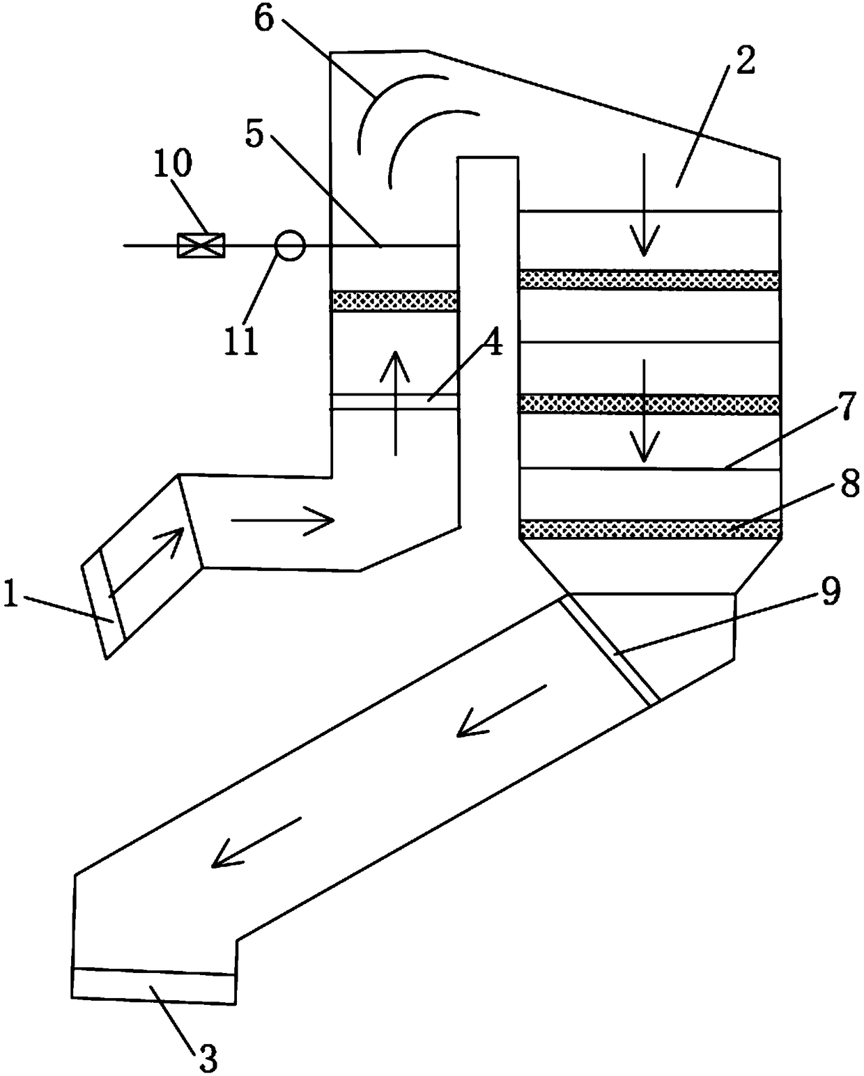
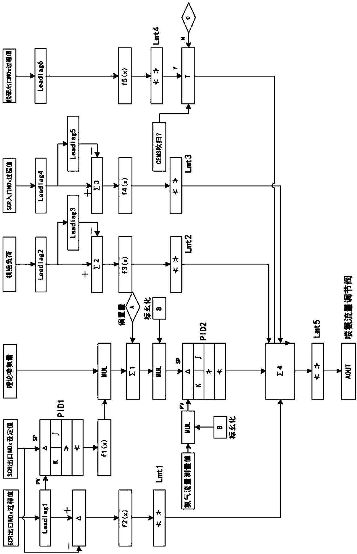
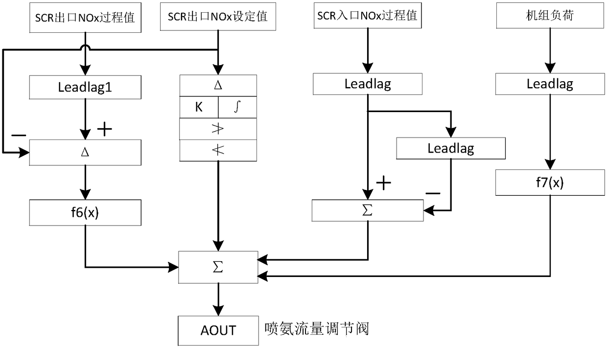
[0036] see figure 1 , the device in this embodiment based on cascade PID plus feed-forward adjustment of denitrification and ammonia injection flow includes SCR reactor 2, electric control valve 10 and flow meter 11, etc., SCR reactor 2 is arranged between boiler economizer 1 and air Between preheaters 3; SCR reactor 2 includes SCR reactor inlet 4, No. 1 ammonia injection grid 5, deflector 6, No. 2 ammonia injection grid 7, catalyst layer 8 and SCR reactor outlet 9; SCR The reactor inlet 4 is arranged adjacent to the boiler economizer 1, and the SCR reactor outlet 9 is arranged adjacent to the air preheater 3; No. 1 ammonia injection grid 5, deflector 6, No. 2 ammonia injection grid 7 and Catalys...


PUM


Abstract

The invention relates to a denitration ammonia spraying flow adjusting device based on cascade PID (proportion integration differentiation) and feedforward and a working method of the device. Existingdenitration ammonia spraying automatic control logic cannot stably control the concentration of NOx at an outlet of an SCR (selective catalytic reduction) reactor, and the labor intensity of operators is increased. The device comprises the SCR reactor, an electric control valve, a flowmeter and the like, wherein the SCR reactor is arranged between a boiler economizer and an air preheater; an inlet of the SCR reactor is adjacent to the boiler economizer, and an outlet of the CR reactor is adjacent to the air preheater; a No.1 ammonia spraying grille, a guide plate, a No.2 ammonia spraying grille and a catalyst layer are sequentially arranged in the flow direction of flue gas, the No.1 ammonia spraying grille is adjacent to the inlet of the SCR reactor, and the No.2 ammonia spraying grilleis adjacent to the catalyst layer. By means of the device, the control problem caused by the large delay characteristic of a denitration system can be solved, control overshoot can be reduced, and accurate control of the ammonia spraying amount can be realized.

Description

technical field [0001] The invention relates to a device and a working method for adjusting the denitrification and spraying ammonia flow based on cascade PID plus feedforward, and belongs to the field of thermal automatic control. Background technique [0002] Under the current background of large-scale grid-connection of new energy sources in the power industry, thermal power units frequently participate in peak regulation, and the depth of peak regulation is increasing. Therefore, the operating condition of the boiler changes frequently in a wide range, resulting in frequent changes of the flue gas parameters at the furnace outlet, including the SCR denitrification inlet NO x Concentrations vary drastically. Selective Catalytic Reduction flue gas denitrification method (Selective Catalytic Reduction), referred to as SCR, is currently the most widely used denitrification method in thermal power plants. The principle of SCR denitrification is to use NH under the action of...

Claims


Application Information

Patent Timeline
Patent Type & Authority Applications(China)
IPC IPC(8): B01D53/78B01D53/56G05B11/42
CPCB01D53/56B01D53/78G05B11/42
Inventor 祝宝营李兵王真宋瑞福邱树良张岩亓振烨张子远
Owner HUADIAN ELECTRIC POWER SCI INST CO LTD
Learn More