Fiber optic sensors for gas turbine control

a technology of fiber optic sensors and gas turbines, applied in the direction of instruments, combustion types, combustion failure safes, etc., can solve the problems of loss of combustion control, heating and melting of combustor parts, and premixed systems are susceptible to unpredictable phenomena, so as to reduce the consequences of systematic and time-variable effects and reduce installation and testing costs

Inactive Publication Date: 2005-12-20
GENERAL ELECTRIC CO
View PDF13 Cites 22 Cited by
  • Summary
  • Abstract
  • Description
  • Claims
  • Application Information

AI Technical Summary

Benefits of technology

[0011]It would be desirable to have a means of quickly detecting the occurrence of a flashback so that a combustor control could react to prevent damage by altering or turning off the combustion; to have an economical sensor that is flexible to bending, light weight, resistant to vibrations, and easy to mount and remove; to have a fiber optic device that can withstand high temperatures and pressures; and to have a method for bundling fibers for high temperature sensing applications.
[0014]In another embodiment of the present invention, an optical fiber device has a bullet tip shape which enables simple fabrication of a sensor head and reduces the escape of hot gases from seal failure.
[0016]In the above embodiments of the present invention, a microprocessor can be used to reduce the consequences of systematic and time variant effects and to reduce the costs of installation and testing.

Problems solved by technology

These premixed systems are susceptible to an unpredictable phenomena commonly referred to as “flashback.” Flashbacks can be caused by any of a number of events, including ignition of impurities in fuel or ignition during mode switching when the flames are in a transient phase.
Both types of flashback occurrences result in a loss of combustion control and can additionally cause heating and melting of combustor parts, such as fuel nozzles, for example, that are not designed to withstand excessive heating.
An operator generally has no method of recognizing the occurrence of a flashback until the combustor sustains damage.
These designs can be bulky, rigid, and expensive because of special components needed for coupling and packaging.
For example, either a very long fiber bundle or a connector with special lenses is required to couple a fiber bundle sensing head to a remote electronic device, and these elements are lossy, bulky, and expensive.
Similar coupling problems exist for sensors involving large diameter sapphire or quartz rods.
Additionally, rods are too rigid to withstand mechanical and thermal stress for large mechanical systems which frequently undergo high temperature thermal cycles.
During machining thermal cycles, dynamic vibrations, installation, and maintenance handling, large rods can crack.
Many packaging techniques, however, cannot withstand temperatures in excess of about 250° C. Commercially available adhesives such as high temperature ultra-violet cured optical epoxies can withstand temperatures up to about 175° C. Quartz tubing fused fiber bundles require heating the bundle to a temperature greater than 1500° C. in order to melt the quartz.

Method used


Image

  • Fiber optic sensors for gas turbine control
  • Fiber optic sensors for gas turbine control
  • Fiber optic sensors for gas turbine control

Examples


Embodiment Construction

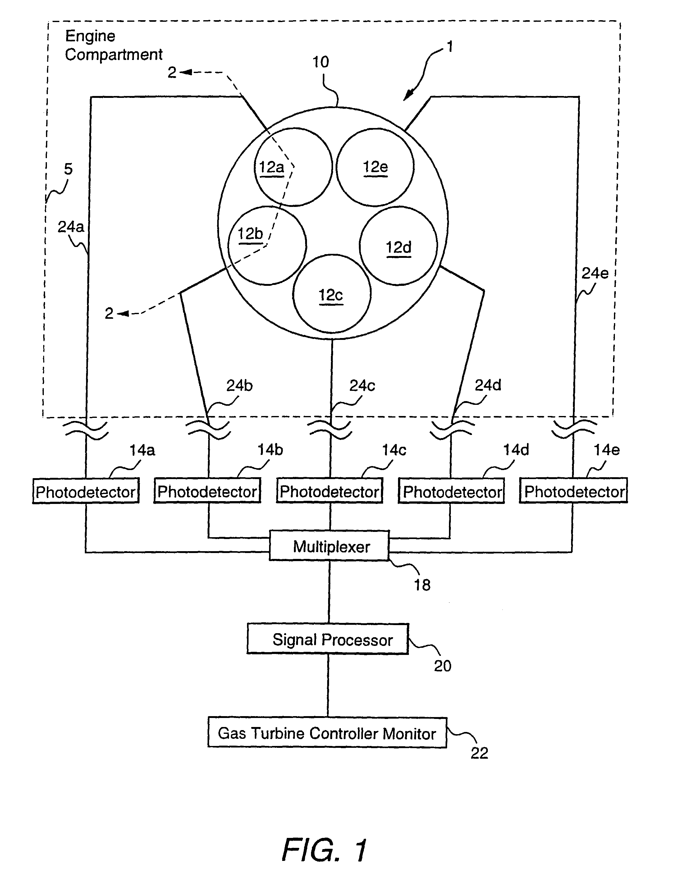
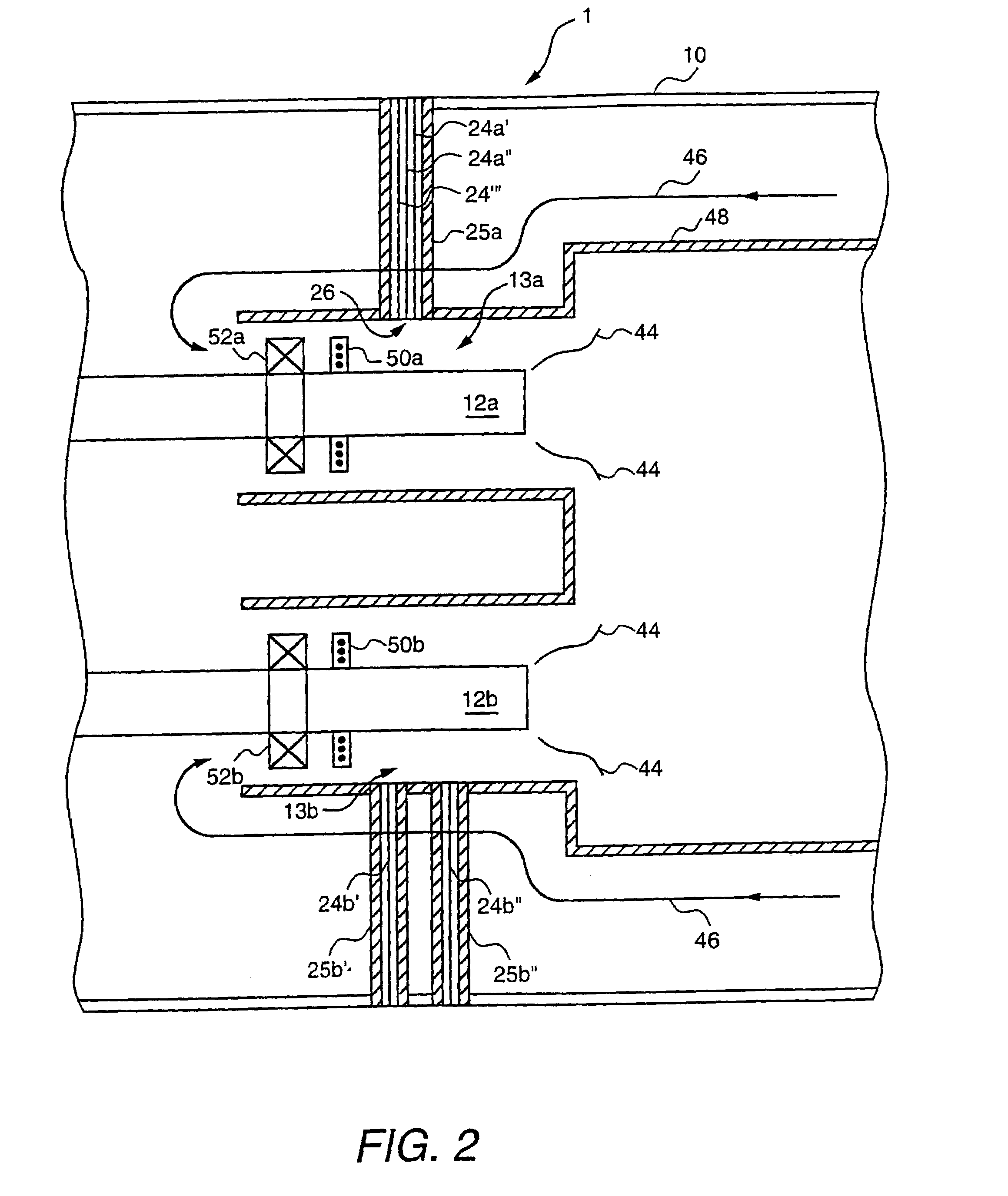
[0028]FIG. 1 is a block diagram of a flashback protection embodiment of the present invention, and FIG. 2 is a sectional view of a portion of the embodiment of FIG. 1.

[0029]A combustor 1 includes at least one fuel nozzle (and preferably a plurality of fuel nozzles 12a, 12b, 12c, 12d, and 12e) capable of supplying flames 44. Each of the fuel nozzles is monitored using a fiber optic element 24a, 24b, 24c, 24d, or 24e comprising at least one respective optical fiber which sends an optical signal to a respective photodetector 14a, 14b, 14c, 14d, or 14e.

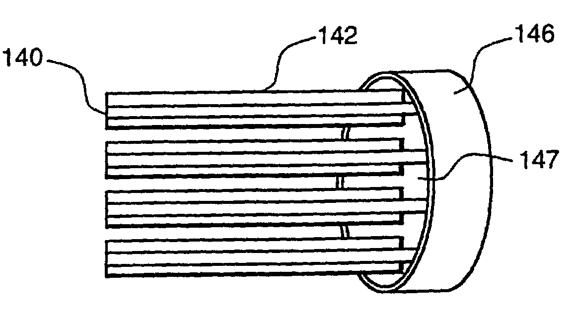
[0030]If desired, each optical fiber optic element 24a, 24b, 24c, 24d, or 24e may comprise several optical fibers in a bundle as shown by optical fibers 24a′, 24a″, and 24a′″ in FIG. 2.

[0031]In one embodiment each fiber optic element includes at least one optical multi-mode fiber pressure-sealed at one end 26 or both ends into a protective tube (shown as tube 25a in FIG. 2) which is capable of withstanding the operating environment. In o...


PUM


Abstract

An apparatus for detecting flashback occurrences in a premixed combustor system having at least one fuel nozzle includes at least one photodetector and at least one fiber optic element coupled between the at least one photodetector and a test region of the combustor system wherein a respective flame of the fuel nozzle is not present under normal operating conditions. A signal processor monitors a signal of the photodetector. The fiber optic element can include at least one optical fiber positioned within a protective tube. The fiber optic element can include two fiber optic elements coupled to the test region. The optical fiber and the protective tube can have lengths sufficient to situate the photodetector outside of an engine compartment. A plurality of fuel nozzles and a plurality of fiber optic elements can be used with the fiber optic elements being coupled to respective fuel nozzles and either to the photodetector or, wherein a plurality of photodetectors are used, to respective ones of the plurality of photodetectors. The signal processor can include a digital signal processor.

Description

[0001]This application is a division of application Ser. No. 09 / 328,354, filed Jun. 9, 1999, now U.S. Pat. No. 6,599,028 which is a divisional of application Ser. No. 08 / 877,341 filed Jun. 17, 1997, now U.S. Pat. No. 5,978,525, which is hereby incorporated by reference in its entirety.[0002]This invention was made with US Government support under contract number NAS327235 awarded by NASA. The Government has certain rights in the invention.BACKGROUND OF THE INVENTION[0003]Gas turbines generally include a compressor, one or more combustors, a fuel injection system and a turbine. Typically, the compressor pressurizes inlet air which is then reverse-flowed to the combustors where it is used to provide air for the combustion process and also to cool the combustors. In a multi-combustor system, the combustors are located about the periphery of the gas turbine, and a transition duct connects the outlet end of each combustor with the inlet end of the turbine to deliver the hot products of c...

Claims


Application Information

Patent Timeline
Patent Type & Authority Patents(United States)
IPC IPC(8): F23D14/72F23D14/82F23N5/08F23R3/28G02B6/36
CPCF23D14/725F23D14/82F23N5/08F23R3/286G02B6/3644F23N2031/28F23N2041/20G02B6/3616G02B6/3664F23N2231/28F23N2241/20
Inventor SHU, EMILY YIXIEPETRUCCO, LOUIS JACOBDAUM, WOLFGANG
Owner GENERAL ELECTRIC CO
Why Eureka
Try Eureka