Multiple spray-head combined type air-injection electrostatic spinning machine

An electrospinning machine and combined technology are applied in the field of multi-nozzle combined air-jet electrospinning machines, which can solve the problems of difficult control of Taylor cone shape, uneven fiber diameter, unstable solution concentration, etc. Simple equipment and high production efficiency

Active Publication Date: 2013-06-26
河南中纤新材料科技有限公司
View PDF14 Cites 17 Cited by
  • Summary
  • Abstract
  • Description
  • Claims
  • Application Information

AI Technical Summary

Problems solved by technology

[0004] The technical problem to be solved by the present invention is to provide a multi-nozzle combined air-jet electrospinning machine, which can be used for mass production of electrospun nanofibers, and overcomes the existing many The needle electrospinning device is easy to block the needle and the output is low, and it also avoids the problems of the Taylor cone shape that is difficult to control, the solvent is volatile, the solution concentration is unstable, and the fiber diameter is not uniform in the current electrospinning device without nozzles.

Method used


Image

  • Multiple spray-head combined type air-injection electrostatic spinning machine
  • Multiple spray-head combined type air-injection electrostatic spinning machine
  • Multiple spray-head combined type air-injection electrostatic spinning machine

Examples


Embodiment 1

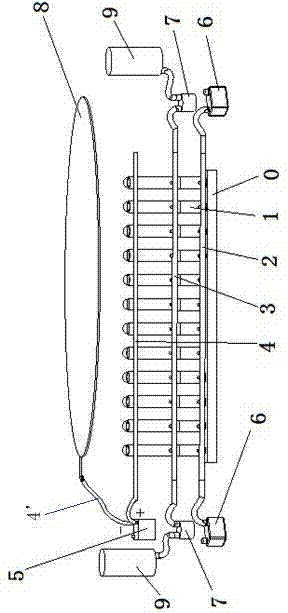
[0024] Example 1: Refer to attached figure 1 And attached Figure 5 , a multi-nozzle combined air-jet electrospinning machine, comprising a base 0, a spinning unit 1, an air pipe 2, an infusion pipe 3, a wire 4, a high-voltage electrostatic generator 5, a cross-flow air pump 6, a metering pump 7, and a receiving electrode Plate 8 and reservoir 9.

[0025] The spinning unit 1 is formed by connecting a spinneret 11 with an air chamber 15 through an intermediate connecting body 14 , and the intermediate connecting body 14 is equipped with a vertically upward air spraying pipe 12 communicating with the air chamber 15 . There is a liquid inlet 13 below the spinneret 11 , the liquid inlet 13 is lower than the upper end surface of the jet pipe 12 , and an air inlet 16 is arranged below the air chamber 15 . A protective ring 10 is installed above the spinneret 11, which can prevent the solution from overflowing during spinning. The inner diameter of spinneret 11 and air chamber 1...

Embodiment 2

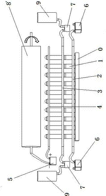
[0029] Example 2: Refer to attached figure 2 And attached Figure 5, a multi-nozzle combined air-jet electrospinning machine, comprising a base 0, a spinning unit 1, an air pipe 2, an infusion pipe 3, a wire 4, a high-voltage electrostatic generator 5, a cross-flow air pump 6, a metering pump 7, and a receiving drum 8' and reservoir tank 9.

[0030] The spinning unit 1 is formed by connecting a spinneret 11 with an air chamber 15 through an intermediate connecting body 14 , and the intermediate connecting body 14 is equipped with a vertically upward air spraying pipe 12 communicating with the air chamber 15 . There is a liquid inlet 13 below the spinneret 11 , the liquid inlet 13 is lower than the upper end surface of the jet pipe 12 , and an air inlet 16 is arranged below the air chamber 15 . A protective ring 10 is installed above the spinneret 11, which can prevent the solution from overflowing during spinning. The inner diameter of spinneret 11 and air chamber 15 is ...

Embodiment 3

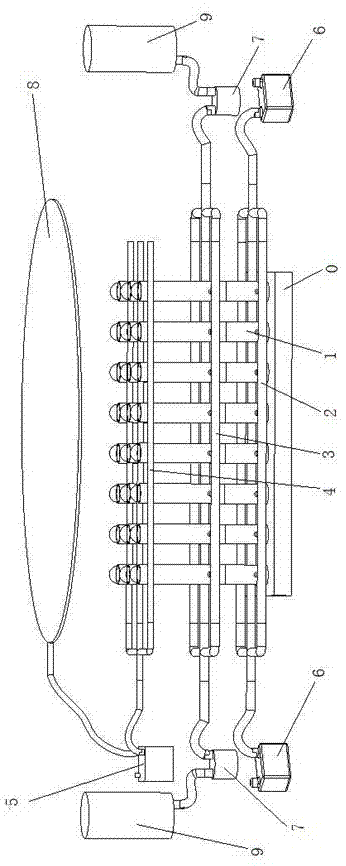
[0034] Embodiment 3: Refer to attached image 3 And attached Figure 5 , a multi-nozzle combined air-jet electrospinning machine, comprising a base 0, a spinning unit 1, an air pipe 2, an infusion pipe 3, a wire 4, a high-voltage electrostatic generator 5, a cross-flow air pump 6, a metering pump 7, and a receiving plate 8 and liquid storage tank 9.

[0035] The spinning unit 1 is formed by connecting a spinneret 11 with an air chamber 15 through an intermediate connecting body 14 , and the intermediate connecting body 14 is equipped with a vertically upward air spraying pipe 12 communicating with the air chamber 15 . There is a liquid inlet 13 below the spinneret 11 , the liquid inlet 13 is lower than the upper end of the jet pipe 12 , and an air inlet 16 is arranged below the air chamber 15 . A protective ring 10 is installed above the spinneret 11, which can prevent the solution from overflowing during spinning. The inner diameter of spinneret 11 and air chamber 15 is ...


PUM

PropertyMeasurementUnit
heightaaaaaaaaaa

Abstract

A multiple spray-head combined type air-injection electrostatic spinning machine is mainly composed of spinning units, an air conveying pipe, a liquid conveying pipe, conductive wires, a high-voltage electrostatic generator, transverse flow air pumps, metering pumps, a receiving device and liquid storage tanks, wherein the spinning units are installed on a base in an inserted mode, air inlets of the spinning units are communicated with the air conveying pipe through air conveying branch pipes, liquid inlets of the spinning units are communicated with the liquid conveying pipe through liquid conveying branch pipes, two ends of the air conveying pipe are communicated with the transverse flow air pumps, and two ends of the liquid conveying pipe are communicated with the liquid storage tanks through the metering pumps; and the receiving device is installed above the spinning unit, metal portions of the spinning units are connected with the positive pole of the high-voltage electrostatic generator through the conductive wires, and the receiving device is connected with the negative pole of the high-voltage electrostatic generator through one conductive wire. The multiple spray-head combined type air-injection electrostatic spinning machine obviously improves the yield of nanofibers, has the advantages of being simple and high in production efficiency, and can achieve continuous and mass production of the nanofibers.

Description

technical field [0001] The invention belongs to the field of fiber processing equipment, and relates to a multi-nozzle combined air-jet electrostatic spinning machine for mass production of nanofibers. Background technique [0002] Electrospinning is a spinning method in which polymer solutions or melts generate jets under the action of a high-voltage electric field to form nanoscale fibers. It is currently the only and most direct method that can continuously prepare organic and inorganic nanofibers. Electrospun nanofibers and their products have the advantages of large specific surface area, small pore size, good air permeability, and wide application range. However, the production efficiency of the traditional single-needle electrospinning device is extremely low, and the output of nanofibers is only between 0.1 and 1.0g / h, which cannot meet the requirements of industrialization. The development of electrospinning technology and Devices are becoming a major target for re...

Claims


Application Information

Patent Timeline
Patent Type & Authority Applications(China)
IPC IPC(8): D01D5/00
Inventor 何建新
Owner 河南中纤新材料科技有限公司
Why Eureka
Try Eureka