Biomass gasification reaction furnace and automatic control method thereof

A gasification reaction and biomass technology, applied in the direction of electrical program control, fixed bed gasification, program control in sequence/logic controller, etc., can solve the problems of waste of raw materials, inability to produce gas, land occupation and construction cost, etc. , to achieve the effects of reducing labor intensity, promoting full cracking, and reducing cost input

Inactive Publication Date: 2013-07-17
山东知周环境科技有限公司
View PDF6 Cites 0 Cited by
  • Summary
  • Abstract
  • Description
  • Claims
  • Application Information

AI Technical Summary

Problems solved by technology

[0002] At present, the most widely used biomass gasifier in the market is a downdraft fixed reaction bed. This kind of gasifier has the following problems: it cannot continuously produce gas, and the gas production efficiency is low
Since it cannot work continuously, it needs to run intermittently, which causes a lot of waste of raw materials when starting and stopping. At the same time, in order to meet the gas consumption of collective cooking, it is necessary to build a large-capacity gas storage device—a gas storage tank, which results in a large amount of land. Occupation and unnecessary increase in station building costs have caused huge waste, and are greatly restricted in application, and cannot be used in many fields such as power generation; poor controllability, difficult to achieve automation, and high labor intensity in operation
[0003] The patent number applied by the applicant is: 2008200257631, and the patent name is: the Chinese patent of biomass gasification gas generator, which solves the above technical problems, realizes continuous gas production in the actual production process, and has high gas production efficiency. But only suitable for diameter less than 0.8m, gas production less than 200m 3 / h gasifier, if the diameter is greater than 0.8m and the gas production is greater than 200m 3 / h gasifier, it is not suitable

Method used


Image

  • Biomass gasification reaction furnace and automatic control method thereof
  • Biomass gasification reaction furnace and automatic control method thereof
  • Biomass gasification reaction furnace and automatic control method thereof

Examples


Embodiment Construction

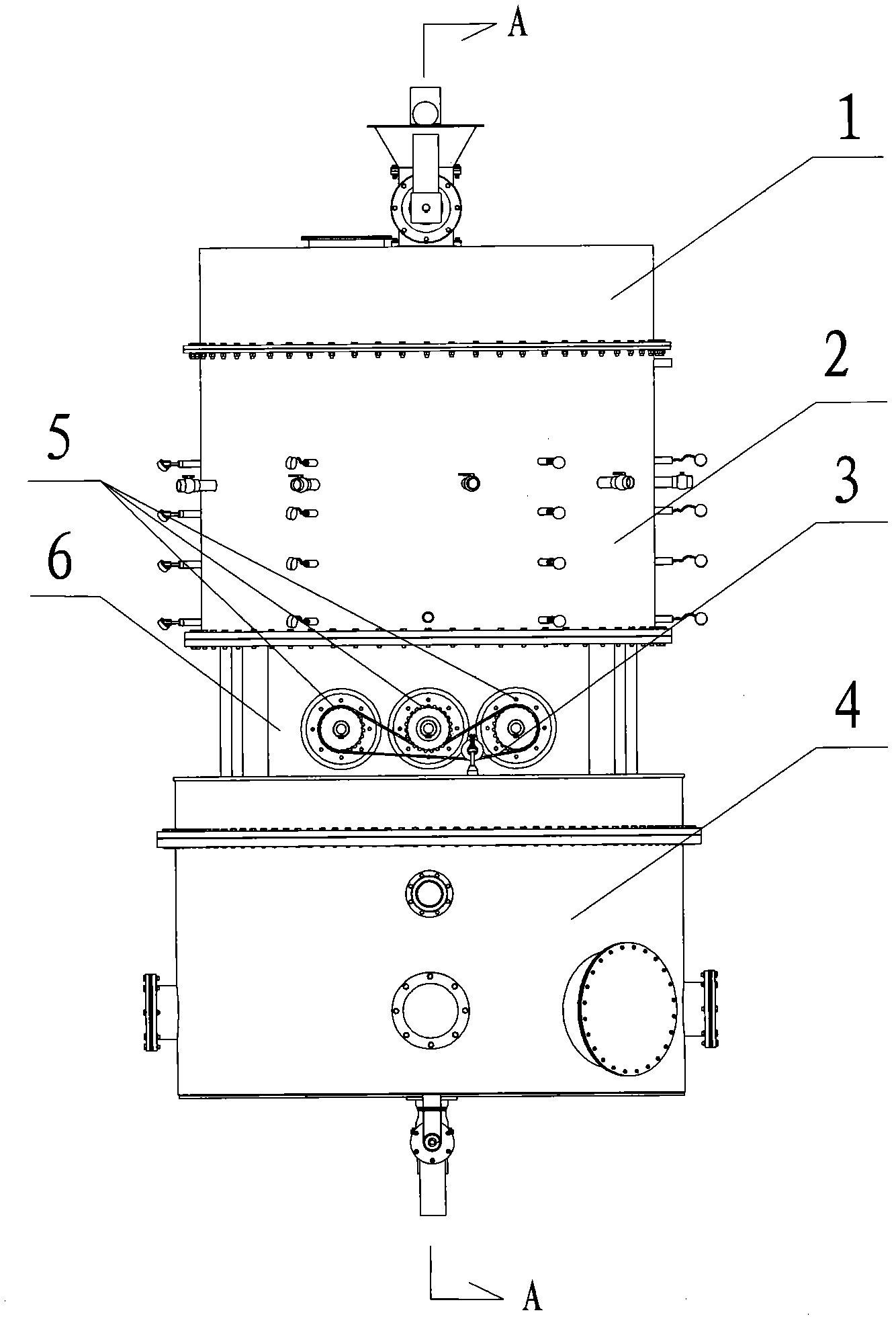
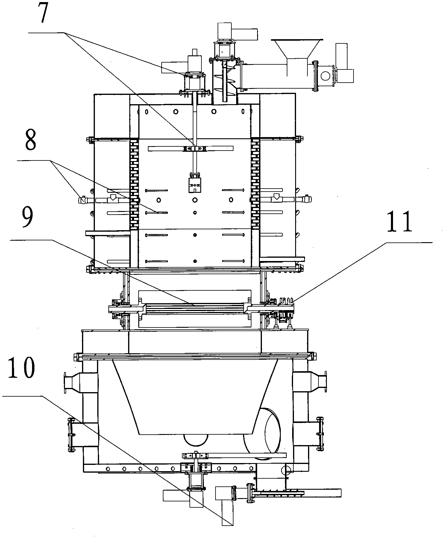
[0039] according to figure 1 and figure 2 As shown, the biomass gasification reaction furnace includes a furnace top 1, a furnace waist 6, a furnace 2, a furnace bottom 4, a fire grate 9, a fire grate rotating transmission device, and a furnace bottom ash discharge sealing device 10, and the fire grate 9 is three Fire grate 9 arranged side by side is formed, and each fire grate 9 is connected with fire grate motor 11 with chain 3 by drive shaft 5 . Furnace top 1 is provided with furnace top stirring air distribution device 7, and furnace 2 is provided with combustion layer air distribution device 8.

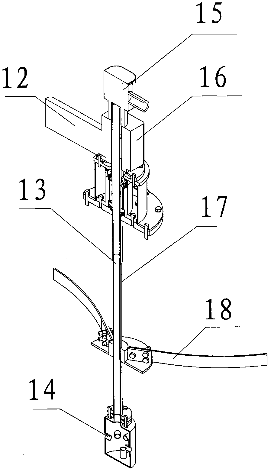
[0040] according to image 3 As shown, the furnace top stirring air distribution device 7 is composed of a motor 12, a reducer 16, a hollow transmission shaft 17 and a stirring blade 18. The upper end of the hollow transmission shaft 17 is connected to the motor 12 and the reducer 16, and the lower end is connected to the stirring blade 18. The top of the shaft 17 is connecte...


PUM


Abstract

The invention belongs to the technical field of biomass gasification reaction equipment, in particular to a biomass gasification reaction furnace and a control method thereof. The technical scheme comprises that: the biomass gasification reaction furnace comprises a furnace roof, a furnace waist, a furnace hearth, a furnace bottom, furnace grates, a furnace grate rotation transmission device and a furnace bottom ash discharging sealing device, wherein the furnace grates consist of at least two furnace grates in parallel arrangement. Due to the rotation of the furnace grate, the ash is discharged to realize broken slag by rolling and extrusion. According to parameters such as material height, material layer (TL), combustion layer (TR), reduction layer (TY), ash layer (TH) and furnace bottom negative pressure (PL), the device can control the height (H) of the combustion layer, and ensure that a driving wind distribution device can exactly and directly perform the wind distribution on the combustion layer.

Description

technical field [0001] The invention belongs to the technical field of biomass gasification reaction equipment, and in particular relates to a biomass gasification reaction furnace and an automatic control method thereof. Background technique [0002] At present, the most widely used biomass gasifier in the market is a downdraft fixed reaction bed. This kind of gasifier has the following problems: it cannot continuously produce gas, and the gas production efficiency is low. Since it cannot work continuously, it needs to run intermittently, which causes a lot of waste of raw materials when starting and stopping. At the same time, in order to meet the gas consumption of collective cooking, it is necessary to build a large-capacity gas storage device—a gas storage tank, which results in a large amount of land. The occupancy and the unnecessary increase in the cost of building a station have caused huge waste, and have been greatly restricted in application, and cannot be used i...

Claims


Application Information

Patent Timeline
Patent Type & Authority Patents(China)
IPC IPC(8): C10J3/20C10J3/34C10J3/72C10J3/06G05B19/04
CPCY02P20/129
Inventor 董磊李景东景元琢强宁刘艳涛张兆玲董玉平张文康
Owner 山东知周环境科技有限公司
Why Eureka
Try Eureka