Eureka AIR delivers breakthrough ideas for toughest innovation challenges, trusted by R&D personnel around the world.

Anchored liner plate

An anchor plate and bearing plate technology, applied in structural elements, building components, building reinforcements, etc., can solve the problems of large volume, high material consumption and high production cost, achieve structural optimization, reduce the number of steel bars cut, and facilitate irrigation dense effect

Inactive Publication Date: 2003-09-17
LIUZHOU OVM MASCH CO LTD
View PDF0 Cites 4 Cited by
  • Summary
  • Abstract
  • Description
  • Claims
  • Application Information

AI Technical Summary

Problems solved by technology

[0003] The technical problem to be solved by the present invention is: to solve the problem that the stress under the concrete anchor of the existing anchor backing plate is large and concentrated, the angle between the steel strands of the outer ring inside the anchor backing plate and the axis is relatively large, the overall size and volume are large, and the material consumption is large. To solve the problems of multiple and high production costs, provide an anchor plate with optimized product structure and improved product performance; the distribution of stress under anchor in the anchorage area is more reasonable, the product has light weight, less material consumption, and low cost.

Method used


Image

  • Anchored liner plate
  • Anchored liner plate
  • Anchored liner plate

Examples


Embodiment Construction

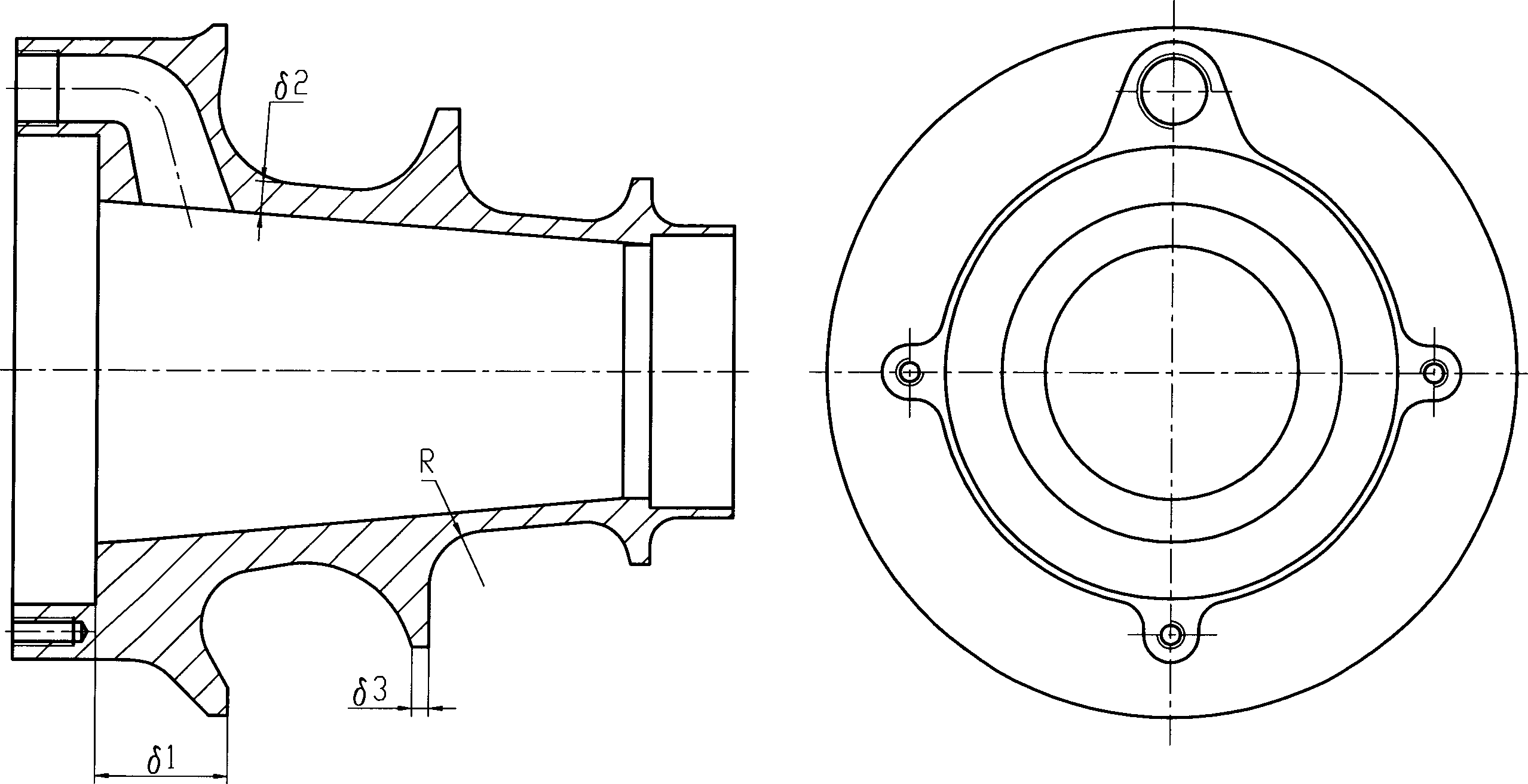
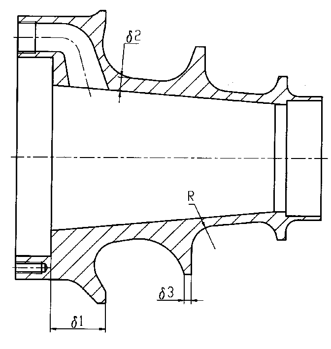
[0013] An anchor pad such as figure 1 Shown: The anchor plate is a round tower-shaped structure with a hollow interior and 2-4 steps in shape. The steps between each step and the tower body are arc-shaped, R=15-50mm, and the tower foot is for sinking anchors. The cylindrical part of the plate, the taper of the hollow tapered hole γ = 2 ~ 5 °, the thickness of the bearing plate δ 1 30-70mm, tower wall thickness δ 2 7 ~ 15mm, step thickness δ 3 7 ~ 12mm, the overall casting shape.


PUM

PropertyMeasurementUnit
Thicknessaaaaaaaaaa
Taperaaaaaaaaaa

Abstract

An anchor shoe is a hollow (2-4)-step circular tower structure with a bearing plate. It has a central conic through hole and a recessed circle for holding anchor plate in it. Said anchor shoe is madeintegrally up by casting. Its advantages are small size, uniform and low stress, light weight, less damage to anchor cable and low cost.

Description

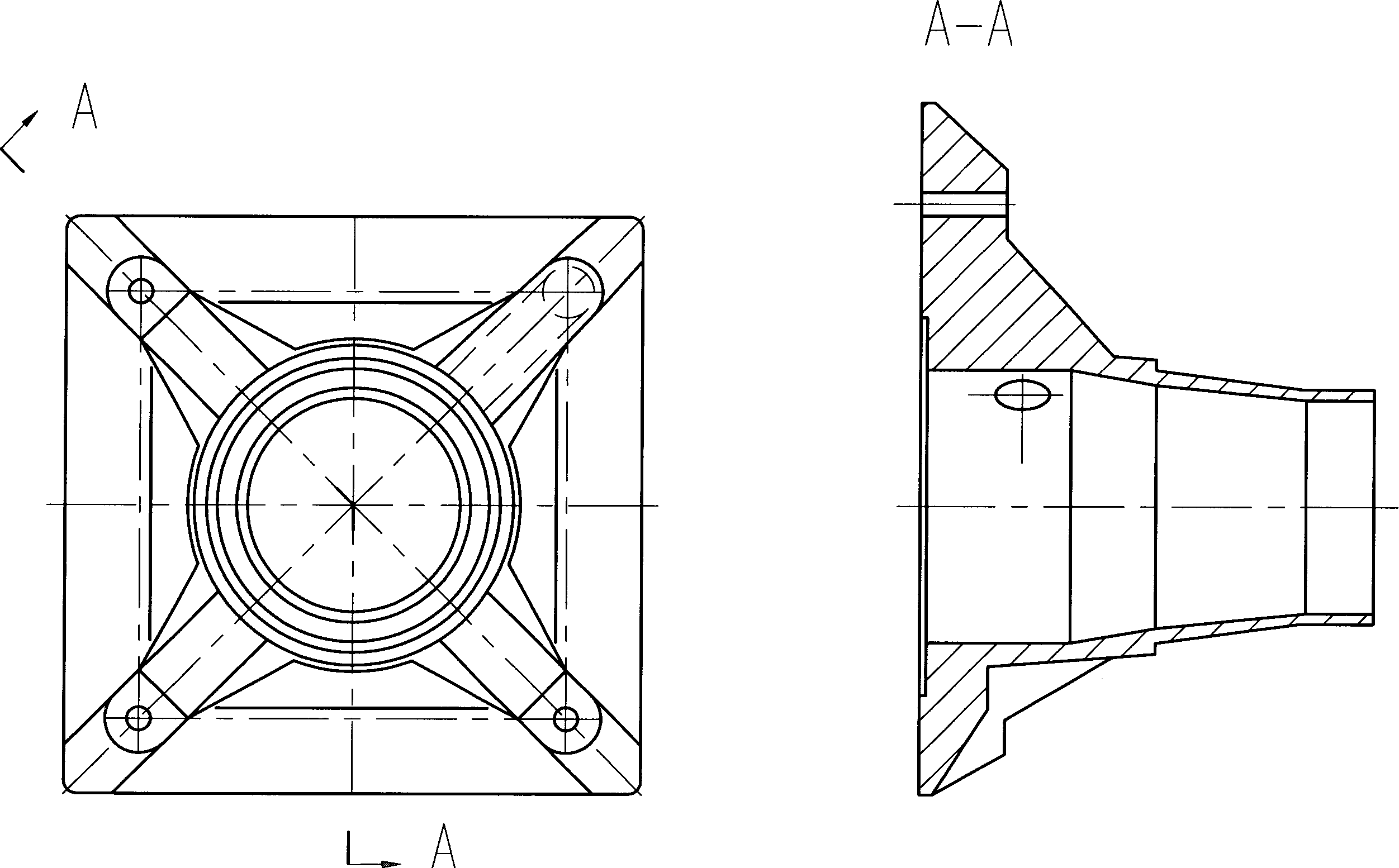
1. Technical field: [0001] The invention relates to a prestressed anchor component, in particular to an anchor plate. 2. Background technology: [0002] Existing anchor pads such as figure 2 As shown, the shape is generally a hollow tower shape, which is composed of a square platform, a round platform and four reinforcing ribs, one of which has a grouting hole; it is integrally cast. The disadvantages of this structure are: firstly, the area of ​​the four-sided platform is too large, the concrete pouring between the lower two ribs is not easy to be compacted, and the number of steel bars on the surface of the anchorage area is too large; secondly, the stress under the concrete anchorage is relatively large, and the stress under the rib tends to Third, inside the anchor plate, the angle between the steel strands of the outer ring and the axis is relatively large, which increases the probability of the steel strands being cut during the tensioning process; fourth, the externa...

Claims


Application Information

Patent Timeline
IPC IPC(8): E04C5/12
Inventor 李国平谢正元毕贵平关炳良强壮秦立方
Owner LIUZHOU OVM MASCH CO LTD
Why Eureka
Eureka Blog
Learn More