Supercharge Your Innovation With Domain-Expert AI Agents!

Cast pipe self anchored interface

A self-anchored, cast pipe technology, which is applied in the direction of pipe/pipe joint/fitting, sleeve/socket connection, passing components, etc., can solve the problems of long construction period, poor pressure bearing capacity of pipeline, poor resistance to radial deformation, etc. Achieve the effects of shortening the auxiliary time, large pressure bearing capacity and preventing radial deformation

Inactive Publication Date: 2003-09-17
XINXING DUCTILE IRON PIPES CO LTD
View PDF0 Cites 6 Cited by
  • Summary
  • Abstract
  • Description
  • Claims
  • Application Information

AI Technical Summary

Problems solved by technology

However, cast pipes can only be constructed one by one during connection and assembly, which is inefficient, and the width of the pipe laying ditch that needs to be dug is large, time-consuming and laborious, and the construction period is long
Due to the construction in the pipe laying ditch, the work is inconvenient and the environment is poor
The paved pipeline has poor pressure bearing capacity and poor resistance to radial deformation
When the temperature of the transported material increases or decreases and the length of the cast pipe changes, it is easy to leak due to the slippage of the socket of the cast pipe
In the construction of pipelines crossing rivers, lakes or over mountains, slippage and leakage occurred many times and rework occurred, which greatly increased the cost and extended the construction period.

Method used


Image

  • Cast pipe self anchored interface
  • Cast pipe self anchored interface
  • Cast pipe self anchored interface

Examples


Embodiment Construction

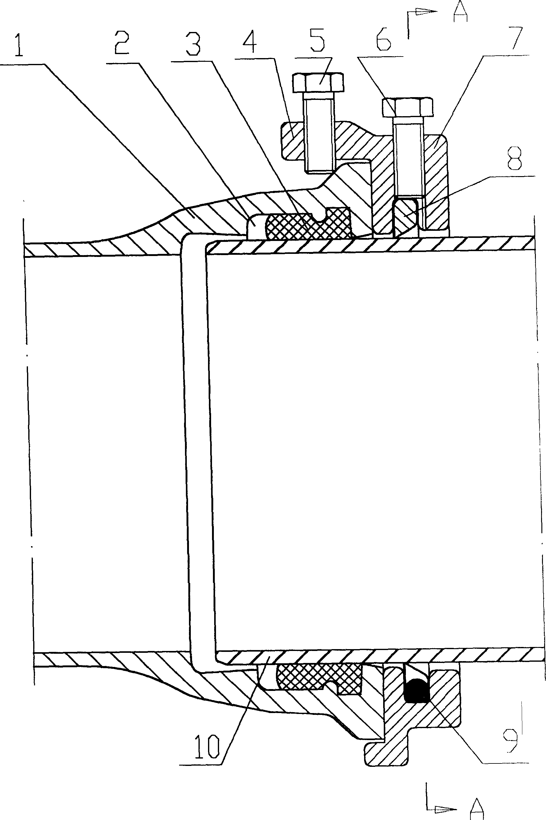
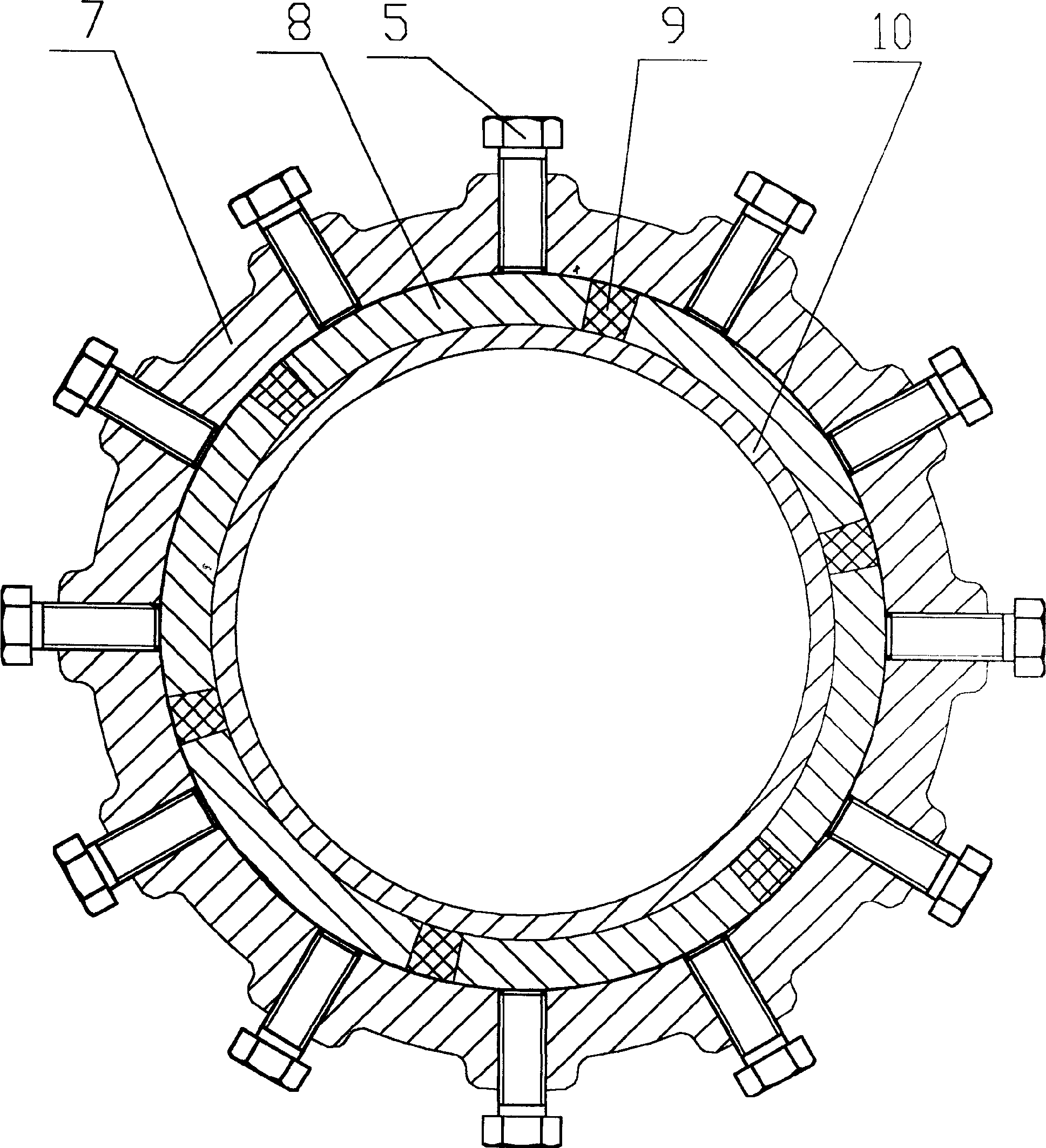
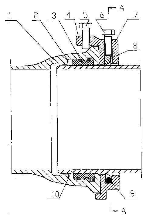
[0009] Put the sealing ring 3 in the inner groove 2 of the socket 1 of the casting pipe, insert the socket 10 of another casting pipe into the socket 1 of the casting pipe, and squeeze the sealing ring 3 tightly on the socket of the casting pipe Between port 1 and socket 10, such as figure 1 , 2 shown. A clamp 7 is sheathed on the outer cylindrical surface close to the junction of the cast pipe socket 1 and the socket 10, the clamp 7 is radially and evenly distributed to lock the threaded hole of the socket 10, and the shoulder 4 of the clamp 7 is radially Evenly distribute the threaded holes of locking socket 1. The threaded hole of the locking socket 10 is a groove near the outer cylindrical surface of the socket 10, and the pressure ring 8 is slidably installed in the groove, and the compression bolt 6 is screwed in the threaded hole of the locking socket 10, and the inner surface of the compression bolt 6 The end is pressed on the pressure ring 8. Tighten the compressi...


PUM


Abstract

A self-anchor joint structure for cast pipes is disclosed. The plug end of one cast pipe is inserted in the socket end of another cast pipe. A sealing ring is tightly pressed in the slot in said socket. A fastening hoop with the screw holes for locking said plug end and socket end is arranged around said joint circumference. The screw bolts are turned in said screw holes to lock the plug end, socket end and fastening hoop together.

Description

(1) Technical field [0001] The invention belongs to an interface structure for connecting TJ-type cast pipes into pipelines. (two), background technology [0002] At present, when the TJ cast pipe is connected into a pipeline, a sealing ring is placed in the inner groove of the socket of the casting pipe, and the socket of another casting pipe is inserted into the socket of the casting pipe, and the sealing ring is tightly squeezed Between the socket and the socket of the cast pipe to achieve sealing and anti-slip. However, cast pipes can only be constructed one by one when they are connected and assembled, and the efficiency is low. The width of the pipe laying ditch that needs to be dug is large, time-consuming and laborious, and the construction period is long. Due to the construction in the pipe laying ditch, the work is inconvenient and the environment is poor. The paved pipeline has poor pressure bearing capacity and poor resistance to radial deformation. When the t...

Claims


Application Information

Patent Timeline
Patent Type & Authority Applications(China)
IPC IPC(8): F16L21/00F16L21/08
Inventor 范英俊杨彬阎炳宽王金秀
Owner XINXING DUCTILE IRON PIPES CO LTD
Features
  • R&D
  • Intellectual Property
  • Life Sciences
  • Materials
  • Tech Scout
  • Unparalleled Data Quality
  • Higher Quality Content
  • 60% Fewer Hallucinations
Learn More