General serial bus equipment

A technology of equipment and host equipment, applied in the direction of measuring devices, instruments, electrical digital data processing, etc., can solve problems such as reduction

Inactive Publication Date: 2003-09-24
FUJIFILM BUSINESS INNOVATION CORP
View PDF0 Cites 24 Cited by
  • Summary
  • Abstract
  • Description
  • Claims
  • Application Information

AI Technical Summary

Problems solved by technology

This method is equivalent to using a proprietary interface, but significantly reduces the advantages of using a standard interface, or USB

Method used


Image

  • General serial bus equipment
  • General serial bus equipment
  • General serial bus equipment

Examples


Embodiment Construction

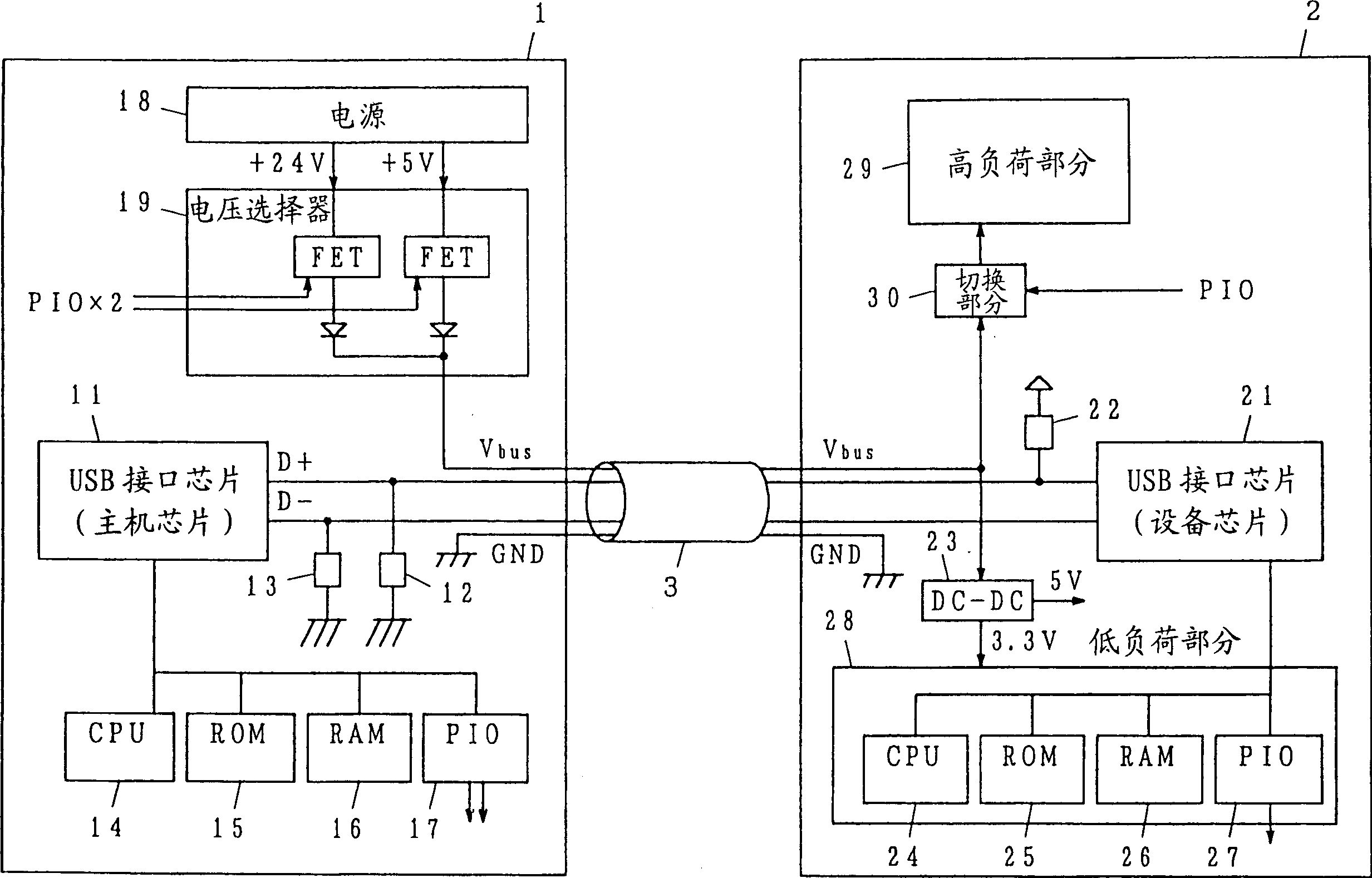
[0021] figure 1 is a block diagram showing an example of a system including a host-side USB device and a device-side USB device as an embodiment of the present invention. In the figure, reference number 1 is host side device, 2 is device side device, 3 is cable, 11 and 21 are USB interface chip, 12, 13 and 22 are resistors, 14 and 24 are CPU, 15 and 25 are ROM, 16 and 26 are RAM, 17 and 27 are PIO, 18 is a power supply, 19 is a voltage selector, 23 is a DC-DC converter, 28 is a low load part, 29 is a high load part, and 30 is a switching part. The host-side device 1 and the device-side device 2 are interconnected by using a cable 3 through a USB interface.

[0022] Host-side device 1 includes: USB interface chip 11 , resistors 12 and 13 , CPU 14 , ROM 15 , RAM 16 , PIO (peripheral I / O) 17 , power supply 18 and voltage selector 19 . The USB interface chip 11 communicates with the device-side device 2 through the data lines D+ and D-. According to the USB standard, resistors...


PUM


Abstract

The invention discloses a USB device which communicates with a second device through a USB interface and simultaneously provides electric power to the second device through a power line in the USB interface. The USB device includes: a communication unit for communicating with the second device; and a power supply capable of outputting electric power whose voltage is different from the standard power supply voltage specified in the USB interface standard. The power supply provides this electrical power to the second device via the power cord. The second device includes a low load unit and a high load unit. The power supply supplies electric power with a supply voltage higher than the standard supply voltage to the high load unit via the supply line.

Description

technical field [0001] The present invention relates to a USB device communicating through a USB interface. Background technique [0002] Recently, the interface specified by the USB standard is widely used. Figure 3A and 3B It is a schematic diagram for roughly explaining the electrical connection when each device is connected with the USB interface. In the figure, reference numeral 31 is a host side device, 32 is a host side interface chip, 33 to 38 are resistors, 35 is a cable, 36 is a device side device, and 37 is a device side interface chip. USB is a four-wire serial interface, and the host-side device 31 is connected to the device-side device 36 through a four-wire cable 35 . The four-core wire is the power wire (Vbus), the ground wire (GND), and the two data wires (D+ and D-). [0003] The data line is connected to the host-side interface chip 32 in the host-side device 31 and the device-side interface chip 37 in the device-side device 36, and is used to transmit...

Claims


Application Information

Patent Timeline
Patent Type & Authority Applications(China)
IPC IPC(8): G06F1/26G06F3/00
CPCG06F1/266G06F2213/0042
Inventor 高桥阳太杉田浩圆部贤一江户川和也金子智一星野勉
Owner FUJIFILM BUSINESS INNOVATION CORP
Why Eureka
Try Eureka