

Method and device for washing base plate
A technology for cleaning devices and substrates, applied in cleaning methods and appliances, cleaning methods using liquids, chemical instruments and methods, etc., can solve the problems of reduced production capacity, uneven cleaning, etc., and achieve the effect of inhibiting the increase of cleaning time
- Summary
- Abstract
- Description
- Claims
- Application Information
AI Technical Summary
Problems solved by technology
Method used
Image

Examples
Embodiment 1
[0066] The substrate cleaning method and cleaning apparatus according to Embodiment 1 of the present invention will be described below with reference to the drawings.
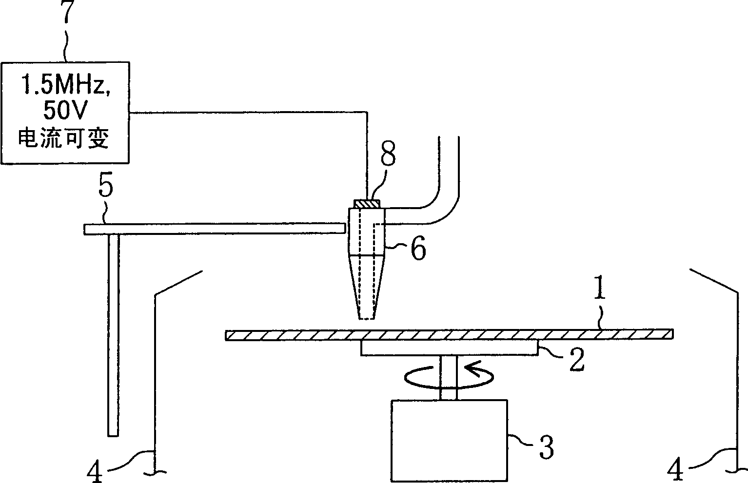
[0067] figure 1 It is a diagram schematically showing the cleaning device of Example 1, specifically, a cross-sectional structure of an ultrasonic cleaning device that cleans the surface of a substrate by supplying a cleaning liquid to which ultrasonic vibrations are applied.
[0068] Such as figure 1As shown, the substrate 1 is sucked and held by the holding part (specifically, a vacuum chuck) 2 . The vacuum chuck 2 is rotationally driven by a motor 3 . The substrate 1 , the vacuum chuck 2 and the motor 3 are accommodated in a cup body (cover) 4 which is open at the top. A nozzle holder 5 is arranged outside the cup body 4 . The front end portion of the nozzle holder 5 is positioned above the substrate 1 inside the cup body 4 . Further, an ultrasonic nozzle 6 that ejects a cleaning liquid such as pure w...
Embodiment 2
[0091] The substrate cleaning method and cleaning apparatus according to Embodiment 2 of the present invention will be described below with reference to the accompanying drawings.
[0092] Figure 9 It is a diagram schematically showing the cleaning device of Example 2, specifically, a cross-sectional structure of an ultrasonic cleaning device that cleans the surface of a substrate by supplying a cleaning liquid to which ultrasonic vibrations are applied. and in Figure 9 , by pairing with figure 1 Components that are the same as those in the cleaning device of the first embodiment shown are given the same reference numerals, and description thereof will be omitted.
[0093] Such as Figure 9 Shown, the cleaning device of the present embodiment and figure 1 The difference between the cleaning apparatus of the first embodiment shown is that a fixed nozzle 20 for supplying cleaning liquid to the center of the substrate 1 is arranged outside the cup body 4 outside the ultra...
Embodiment 3
[0102] The substrate cleaning method and cleaning apparatus according to Embodiment 3 of the present invention will be described below with reference to the accompanying drawings.
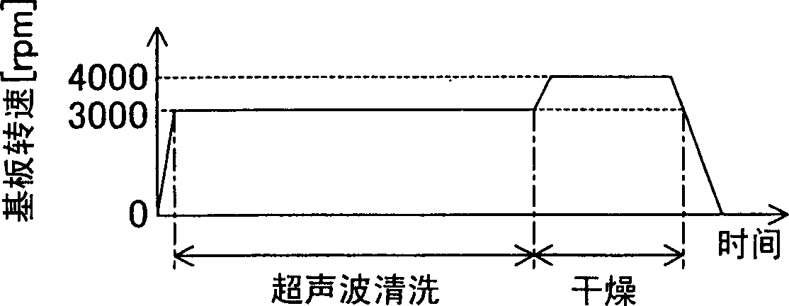
[0103] And, the basic structure of the cleaning device of the present embodiment and the cleaning sequence are the same as the basic structure of the cleaning device of Embodiment 1 (refer to figure 1 ) and cleaning sequence (see image 3 ) are the same, so the description is omitted.
[0104] Figure 12 It is a plan view schematically showing the scanning range of the ultrasonic nozzle 6 (hereinafter referred to as the nozzle scanning range) in the ultrasonic cleaning device of this embodiment.
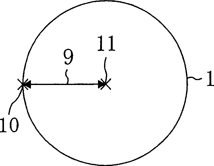
[0105] Such as Figure 12 As shown, the nozzle scanning range of this embodiment is the same as figure 2 The differences in the nozzle scanning ranges of the shown embodiment 1 are as follows. That is, if figure 2 As shown, the nozzle scanning range 9 of Embodiment 1 is set in the radial directio...
PUM
 Abstract
Description
Claims
Application Information