Indicator and its drive method

A display and data driver technology, applied in static indicators, instruments, electrical solid devices, etc., can solve problems such as difficulty in distinguishing data voltage from another data voltage, and grayscale reduction.

Inactive Publication Date: 2003-10-08
SAMSUNG DISPLAY CO LTD
View PDF0 Cites 53 Cited by
  • Summary
  • Abstract
  • Description
  • Claims
  • Application Information

AI Technical Summary

Problems solved by technology

If the threshold voltage varies in the range of 100mV, which is often the case, it will be difficult to distinguish one data voltage from another, and as a result, the gray scale is reduced

Method used


Image

  • Indicator and its drive method
  • Indicator and its drive method
  • Indicator and its drive method

Examples


Embodiment Construction

[0032] Hereinafter, the same components are denoted by the same reference numerals. When a component is connected to another component, the component is not only directly connected to the other component, but also electrically connected to the other component with another element interposed therebetween.

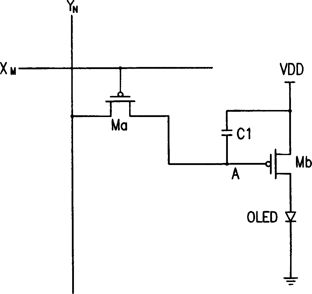
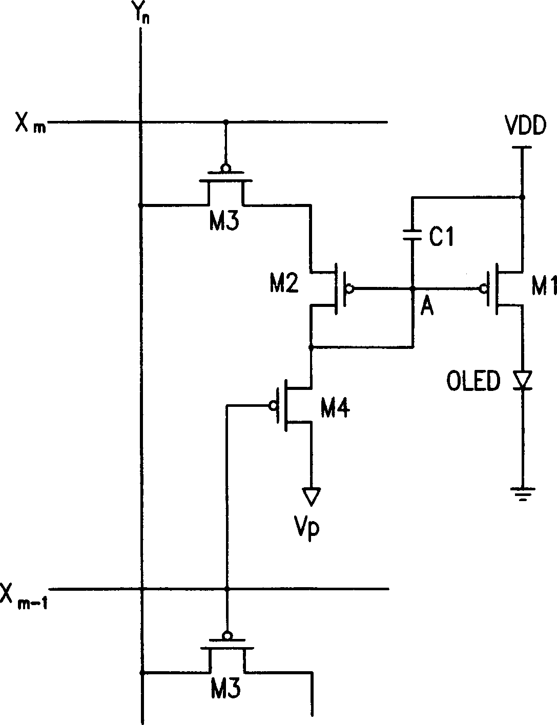
[0033] First, refer to figure 2 , Figure 3A ,with Figure 3B , the organic EL display and its driving method according to the first embodiment of the present invention will be described.

[0034] figure 2 represents the organic EL display according to the first embodiment of the present invention, Figure 3A with Figure 3B Typical pixels according to the first embodiment and the modified example of the present invention are shown.

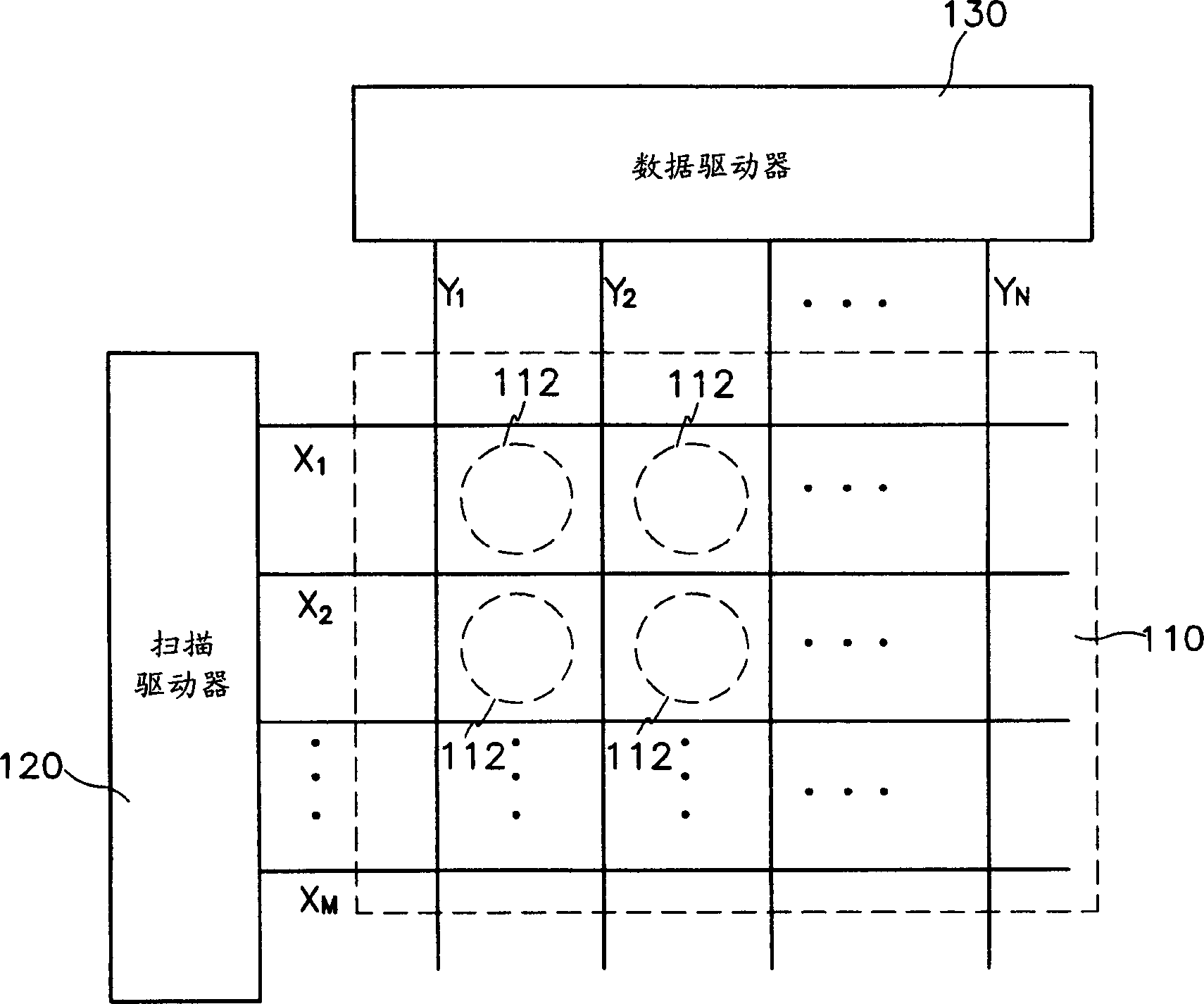
[0035] Such as figure 2 As shown, the organic EL display according to the first embodiment of the present invention includes an organic EL display panel 110 , a scan driver 120 , and a data driver 130 .

[0036] The organic EL display ...


PUM


Abstract

In a display, capacitors are charged with first precharge voltages at the time of applying selection signals to previous scan lines. A data driver divides a plurality of data lines into a plurality of groups each of which consists of at least one data line and applies corresponding data voltages to the data lines of respective groups sequentially. The display further includes a precharge means, and such precharge means applies second precharge voltages to data lines of at least one group before selection signals for selecting scan line are applied to the scan line connected to the pixel circuits and stops application of the second precharge voltages before corresponding data voltages are applied to the respective groups. In this way, it is possible to solve the problem of poor images due to charge redistribution of the capacitors caused by previous data voltages stored in parasitic capacitors.

Description

[0001] This application claims priority and benefits from Application No. 2002-0015437 filed with the Korean Industrial Property Office on March 21, 2002, the entire disclosure of which is hereby incorporated by reference. technical field [0002] The present invention relates to a display and its driving method, in particular to an organic electroluminescence (electroluminescence, hereinafter referred to as "EL") display with an active matrix driving method. Background technique [0003] In general, an organic EL display is a display that emits light by electronic excitation of a fluorescent organic compound and displays an image by driving each of M×N organic light emitting units using voltage or current. [0004] The organic unit has an anode structure (ITO), an organic thin film and a cathode layer (metal). The organic thin film is constructed as a multi-layer structure including an emission layer ("EML", emission layer), an electron transport layer (ETL, electron transp...

Claims


Application Information

Patent Timeline
Patent Type & Authority Applications(China)
IPC IPC(8): H01L51/50G09G3/20G09G3/30G09G3/32
CPCG09G3/3291G09G2300/0842G09G2320/043G09G2310/0262G09G2300/0809G09G2310/0251G09G3/3233G09G2300/0819G09G2310/0297G09G2310/0248G09G3/30
Inventor 申东蓉权五敬
Owner SAMSUNG DISPLAY CO LTD
Why Eureka
Try Eureka