
Sewing machine with cloth cutter

A sewing machine and cutter technology, applied in the field of sewing machines, can solve problems such as difficulty in determining the correct position

Inactive Publication Date: 2003-10-29
YAMATO SEWING MASCH MFG CO LTD
View PDF0 Cites 5 Cited by
  • Summary
  • Abstract
  • Description
  • Claims
  • Application Information

AI Technical Summary

Problems solved by technology

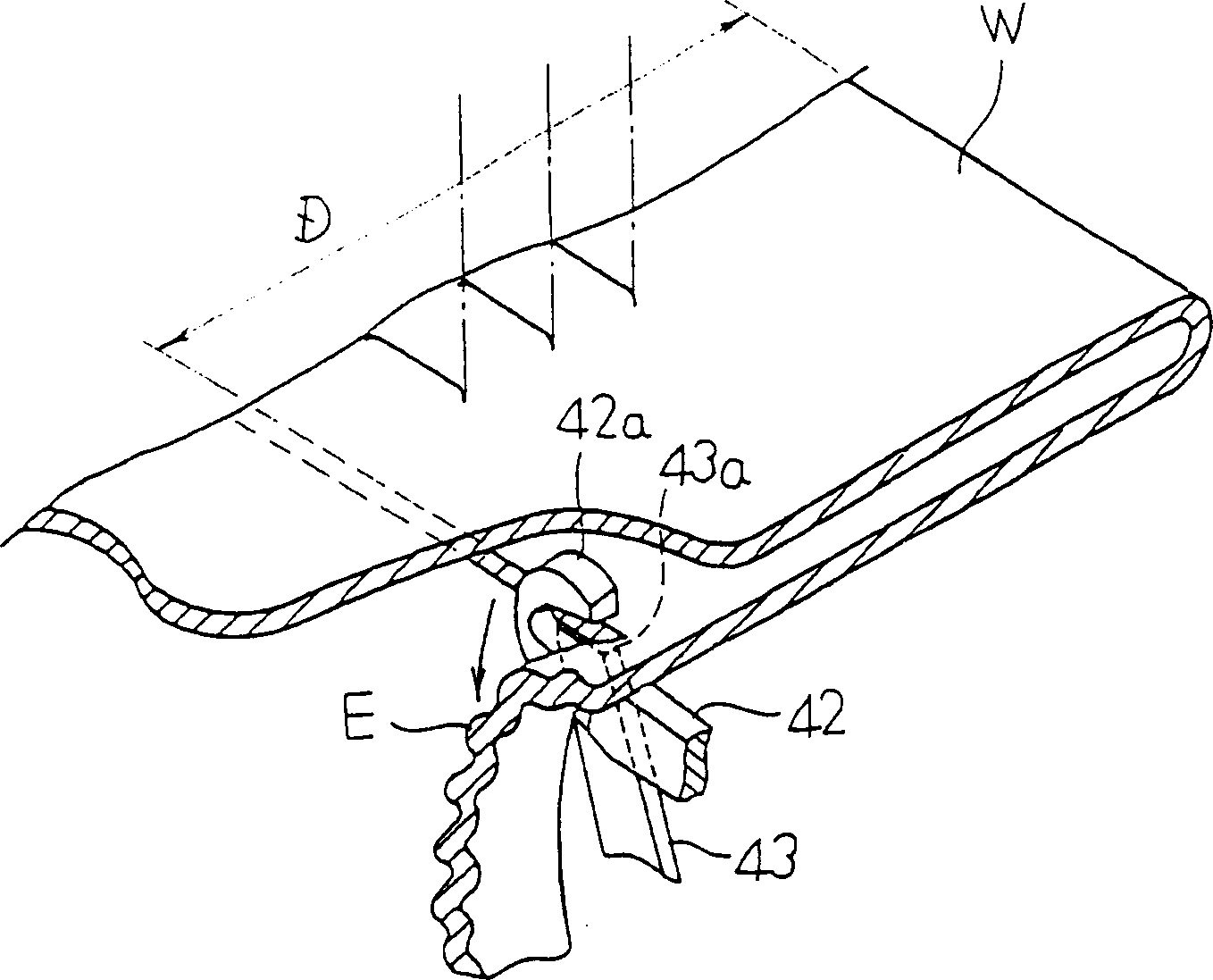
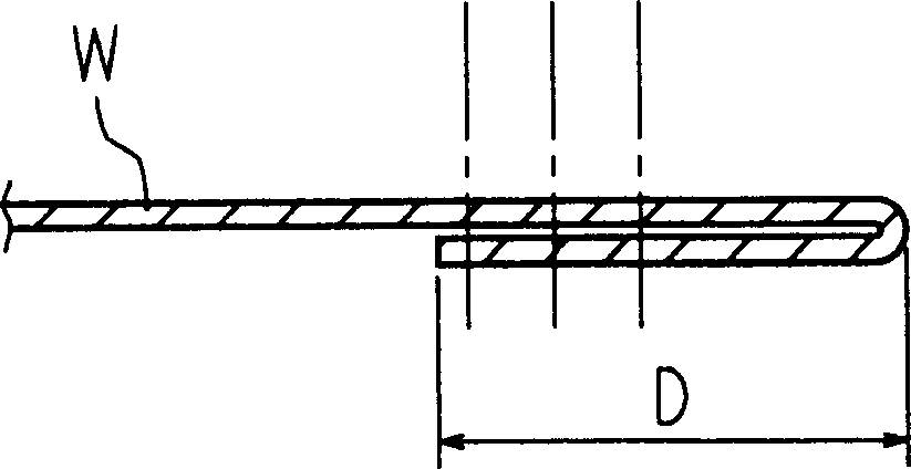
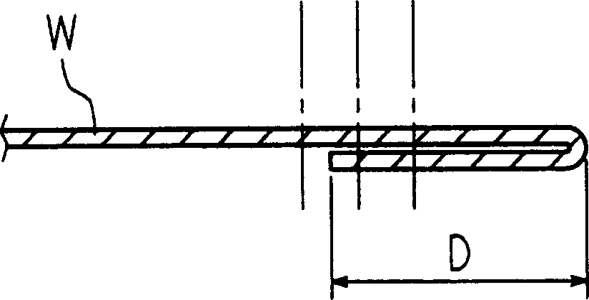
However, in this method, it is difficult to determine the correct position. After the trial sewing, the position must be changed again, and there is a problem that a lot of manpower is required to obtain the desired folding width D.

Method used


Image

  • Sewing machine with cloth cutter
  • Sewing machine with cloth cutter
  • Sewing machine with cloth cutter

Examples


Embodiment Construction

[0026] specific implementation

[0027] Hereinafter, the present invention will be described in detail based on drawings showing preferred embodiments. image 3 It is a perspective view of the overall structure of the sewing machine with the cutter according to the present invention.

[0028] The illustrated sewing machine is a flat seam sewing machine having a sewing machine arm A at the bottom supported by a leg part C established on the upper surface of the sewing machine bed B. As shown in FIG. A plurality of needles 1, 1 . Also, on the front end portion of the sewing machine B facing below the needles 1, 1..., a needle plate (Stitch Plate) 3 is erected, and an unillustrated looper (Looper) and a feeding mechanism are arranged on the bottom of the needle plate 3. (Feed Mechanism).

[0029] The above-mentioned needles 1, 1... are transmitted from an unshown upper shaft built in the arm of the sewing machine, and together with the above-mentioned needle bar, move up and d...


PUM


Abstract

A sewing machine with a cutter, which supports the cutter shaft of the movable cutter, and supports the cutter stand on which the fixed cutter is installed on the base base in a foldable and movable manner in the direction of the shaft length through a support cylinder protruding from one side. On the support frame, on the rear side of the cutting table and the support frame, cooperate with the screw shaft screwed in the screw hole of the sewing machine base, and engage the operation dial set on the screw shaft with the surrounding support tube The engaging groove of the cutting board constitutes an adjustment device, and the shaft screw is screwed in by operating the dial, which can easily and accurately adjust the position of the cutting table in the left and right directions, and can flexibly correspond to the change of the cutting position of the sewn fabric .

Description

technical field [0001] The present invention relates to a sewing machine (Sewing Machine) with a knife, which includes a movable knife, which is sent to cut off the needle drop position on the sewing machine base in a state of crossing a predetermined width and folding back on the back. The edge of the cloth that enters, and the side at the front of the needle drop position enters and exits from the inside of the sewing machine base; and the fixed cutter is slid on one side of the movable cutter. Background technique [0002] For example, in sewing T-shirts, when the tubular part is provided around the waist or at the cuffs, the edge of the fabric to be targeted is brought to the needle drop position in a state of being folded back across a predetermined width. , to implement the folded edge to meet the crease on the surface side of the fabric. [0003] Due to the implementation of this folding seam, in the prior art, the sewing machine with a cutting knife used is to move ...

Claims


Application Information

Patent Timeline
Patent Type & Authority Applications(China)
IPC IPC(8): D05B37/06D05B37/08
Inventor 三辻登四郎
Owner YAMATO SEWING MASCH MFG CO LTD
Learn More