

Multifunctional electric energy converter
A power converter and multi-functional technology, applied in the direction of output power conversion device, irreversible DC power input into AC power output, electrical components, etc., can solve the problems of large volume, heavy weight and high cost of the inverter , achieve the effect of volume and weight reduction, simple structure and cost reduction
- Summary
- Abstract
- Description
- Claims
- Application Information
AI Technical Summary
Problems solved by technology
Method used
Image

Examples
Embodiment Construction
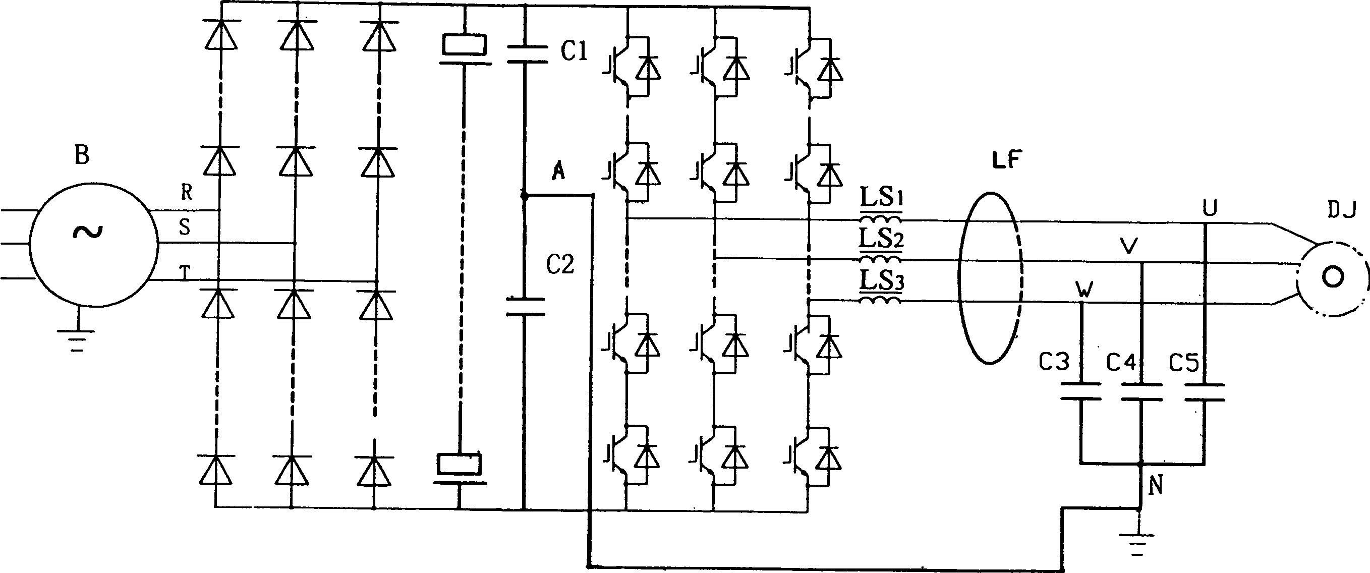
[0011] Such as figure 1 As shown, the specific composition of the multifunctional power converter includes a rectifier circuit, a filter circuit connected to the rectifier circuit, an inverter circuit connected to the filter circuit, and connected in series on the output lines U, V, and W of the inverter circuit respectively. The differential mode voltage suppression reactor LS 1 、LS 2 、LS 3 And the filter capacitor group, the filter capacitor group is connected in series with the capacitors C on the U, V, W output lines respectively 3 、C 4 、C 5 form, capacitance C 3 、C 4 、C 5 The other end of the parallel connection constitutes a midpoint N, in the differential mode voltage suppression reactor LS 1 、LS 2 、LS 3 and filter capacitor bank C 3 、C 4 、C 5 A closed magnetic ring LF is provided on the output lines U, V, W of the inverter circuit between them, and the closed magnetic ring is set in such a way that the output lines U, V, W are simultaneously wound on the c...
PUM
 Abstract
Description
Claims
Application Information