Thermal treatment method of metal tube and said thermal treatment apparatus

A technology of heat treatment method and heat treatment device, applied in the direction of heat treatment furnace, heat treatment equipment, improvement of process efficiency, etc.

A technology of heat treatment method and heat treatment device, applied in the direction of heat treatment furnace, heat treatment equipment, improvement of process efficiency, etc.

CN1455005AInactive Publication Date: 2003-11-12DAI ICHI HIGH FREQUENCY

Image

  • Thermal treatment method of metal tube and said thermal treatment apparatus
  • Thermal treatment method of metal tube and said thermal treatment apparatus
  • Thermal treatment method of metal tube and said thermal treatment apparatus

Examples


Embodiment Construction

[0029] Although the implementation of the present invention may not consider the purpose and material of the metal cylinder, the main purpose of the cylinder is rolls and rotating shafts, and the main material can be carbon steel, low alloy steel, mold steel, high-speed steel or stainless steel. .

[0030] Here, first, an apparatus used for carrying out the present invention will be described.

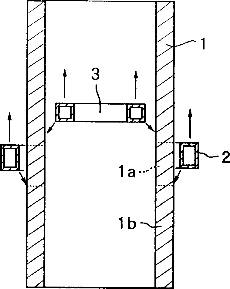
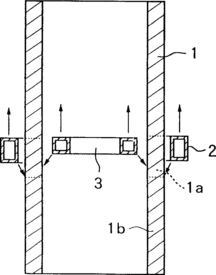
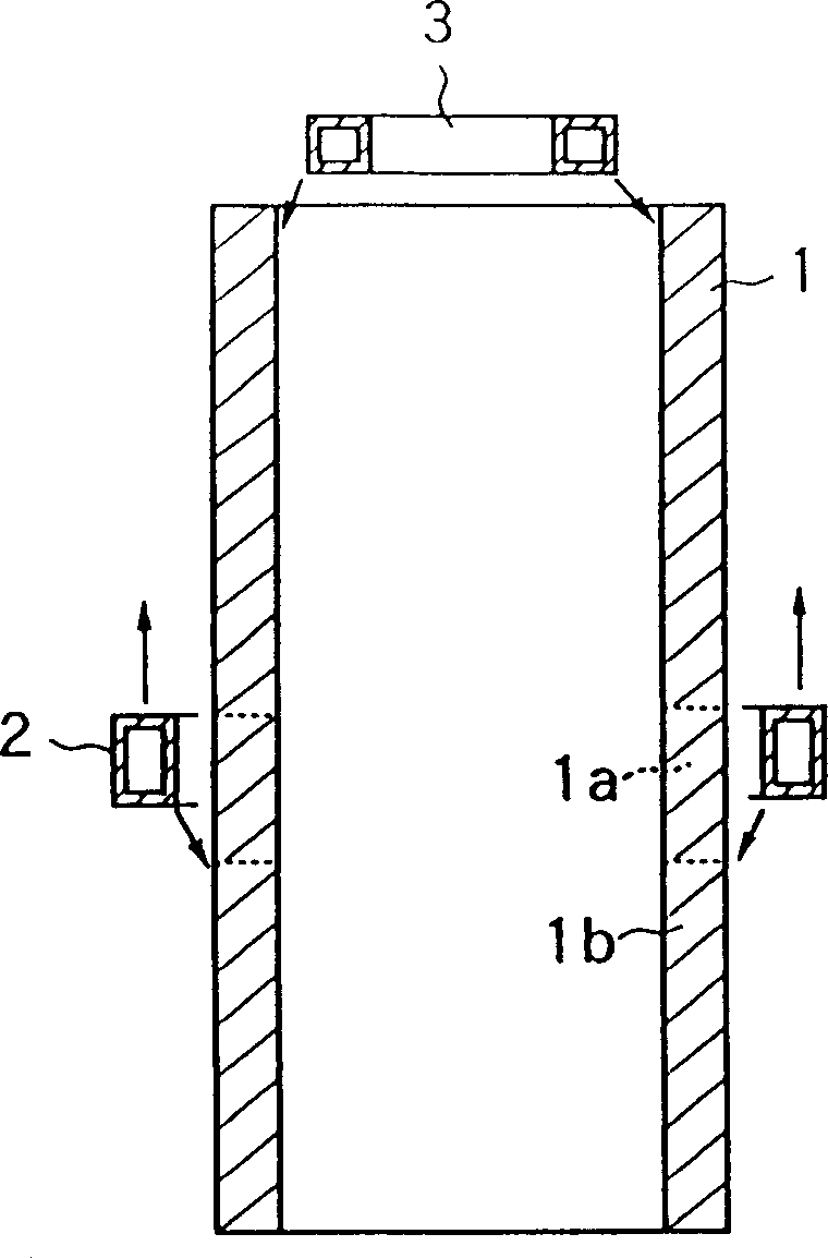
[0031] figure 1 Taking an example of the device for implementing the present invention as a model to show its front sectional view, on the outer surface side, the axial small area 1a of the metal cylinder 1 is inductively heated to the heat treatment temperature by the heating coil 2 surrounding it, and this heating operation is performed by The lower end of the cylindrical body is continuously advanced to the upper end. At the same time, the cooling device 2a that injects cooling water in the coil from the small hole group 2aa provided on the coil cools the rear end side adjacent ar...


PUM


Abstract

The present invention provides a heat-treatment technique. It is characterized by that when said invention adopts a continuous mobile inductive heating and cooling operation mode to treat the external surface of workpieces of roll, etc., at the same time it can inhibit the outer diameter deformation due to heat treatment. At the same time of making heat treatment of external surface of said workpiece of roll, etc. the inner surface of said workpiece can be cooled, and the depth of penetration of the induced current in the induction heating process can be limited in a certain range to reduce deformation of its outer diameter.

Description

technical field [0001] The present invention relates to the technology of performing heat treatment such as quenching on the outer surface of a metal cylinder represented by a hollow roll shell workpiece that is often used in a metal plate processing production line by using induction heating, and provides a technology that can reduce the occurrence of heat treatment during the heat treatment process. A heat treatment method and a device used in the method for achieving a desired heat treatment depth by deforming the outer diameter of a cylinder with high power efficiency. Background technique [0002] In the past, the heat treatment of metal cylinders such as hollow roll shells using induction heating was done in Figure 7 In the state shown in , that is, on the outer surface side of the metal cylinder 1, the heating coil 2 surrounding the cylinder 1 and the small section 1a along the axial direction of the cylinder is arranged, and the coil is fed into the The high-frequen...

Claims


Application Information

Patent Timeline
12 Nov 2003
Publication
CN1455005A
IPC
C21D1/10; C21D9/38
CPC
Y02P10/25
Inventors
松原洋一; 永沼敏彦