
Program switch

A switch and program technology, applied in the direction of electric switches, electrical components, circuits, etc., can solve the problems of elastic fatigue, no pressing point, and the state of the connection is easily affected by external forces.

Inactive Publication Date: 2003-12-03
EXCEL CELL ELECTRONICS
View PDF0 Cites 2 Cited by
  • Summary
  • Abstract
  • Description
  • Claims
  • Application Information

AI Technical Summary

Problems solved by technology

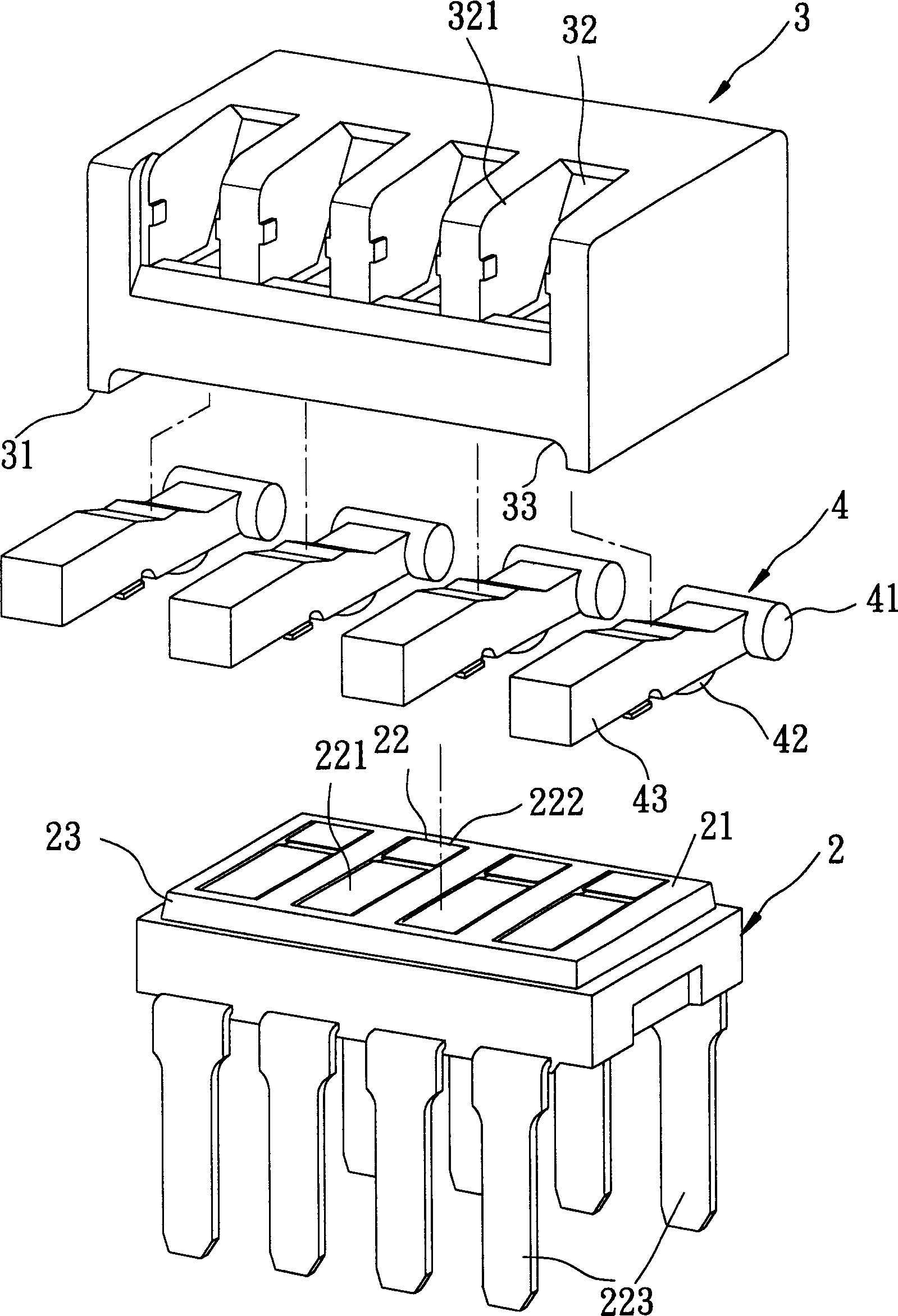
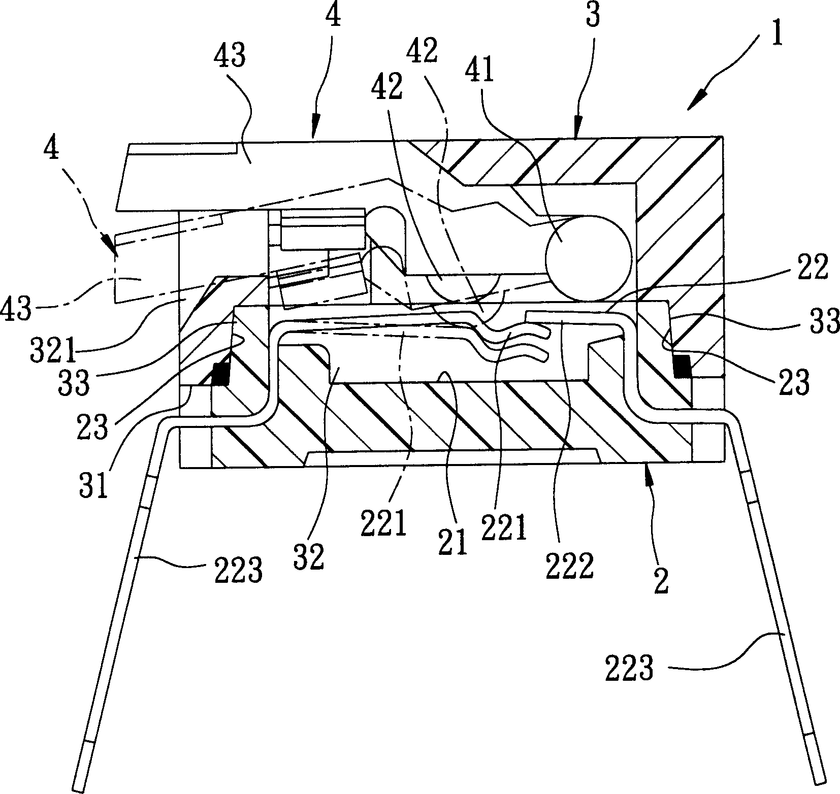
[0008] 1. The metal domes 22 of the program switch 1 are made of common copper materials, and the up and down movement of the toggle block 43 is used to control the mutual connection state of the long domes 221 and the short domes 222 , but after long-term use, because generally copper is prone to elastic fatigue, causing the elastic recovery of the long elastic pieces 221 to be in an unstable state, so that the connection state between the long elastic pieces 221 and the short elastic pieces 222 is easily affected by external forces , and a malfunction occurs
[0009] 2. The programmable switch 1 uses a longer force arm to abut against a shorter force arm from bottom to top by its elasticity. By moving the toggle parts 4 up and down, the long elastic pieces 221 and the The short elastic pieces 222 form a shape of being pressed against each other or separated from each other, and the long elastic pieces 221 need a larger elastic recovery force to abut against the short elastic pieces 222 due to the influence of a longer moment arm. After long-term use, it is easy to Elastic fatigue occurs, making the program switch 1 prone to misoperation
[0010] 3. Because the long elastic pieces 221 and the short elastic pieces 222 form a mutual crimping or detachment shape, a stable pressing point is not obtained during assembly. When the industry uses related machines for automated mass production, because the The non-stable pressure point design of the equal-length elastic pieces 221 and the short elastic pieces 222 is prone to produce defective products, which relatively causes waste of manufacturing costs and man-hours, that is, it does not meet the purpose of automatic production to reduce manufacturing costs

Method used


Image

  • Program switch
  • Program switch
  • Program switch

Examples


Embodiment Construction

[0023] Such as Figure 4 , 5 As shown, a better embodiment of the present invention includes a base 5, an upper cover 6 that can be snapped and sealed on the base 5, a metal shrapnel 7 mounted on the base 5, and the number can be displaced up and down. The toggle piece 8 pivotally mounted in the upper cover, in this example, four metal domes 7 and four toggle pieces 8 are used.

[0024] The base 5 is made of an insulating material such as rubber or plastic, and has a top surface 51, a number of rectangular actuating grooves 52 parallel to the width direction of the top surface 51 and recessed downwards. In the example, the base 5 has four actuating grooves 52, and two opposite sidewalls 53 extending downward along the width direction of the top surface 51. The notch is fixed with several wing plates 54, and the top surface 51 is respectively fixed with a rectangular fixed block 55 along its length direction and adjacent to the notch of these actuating grooves 52, and the bot...


PUM


Abstract

A programming switch is composed of a base with several recesses having parallel but non-contact two metallic sheets for each recess, a top cover embedded to the base, several metallic elastic pieces fixed to said base, and several toggle parts pivoted in the top cover and with a convex block for touching with said metallic elastic piece. When said toggle part moves up and down, a metallic elastic piece is driven to touch with one or both side metallic sheets. Its advantages are long service life, and low cost.

Description

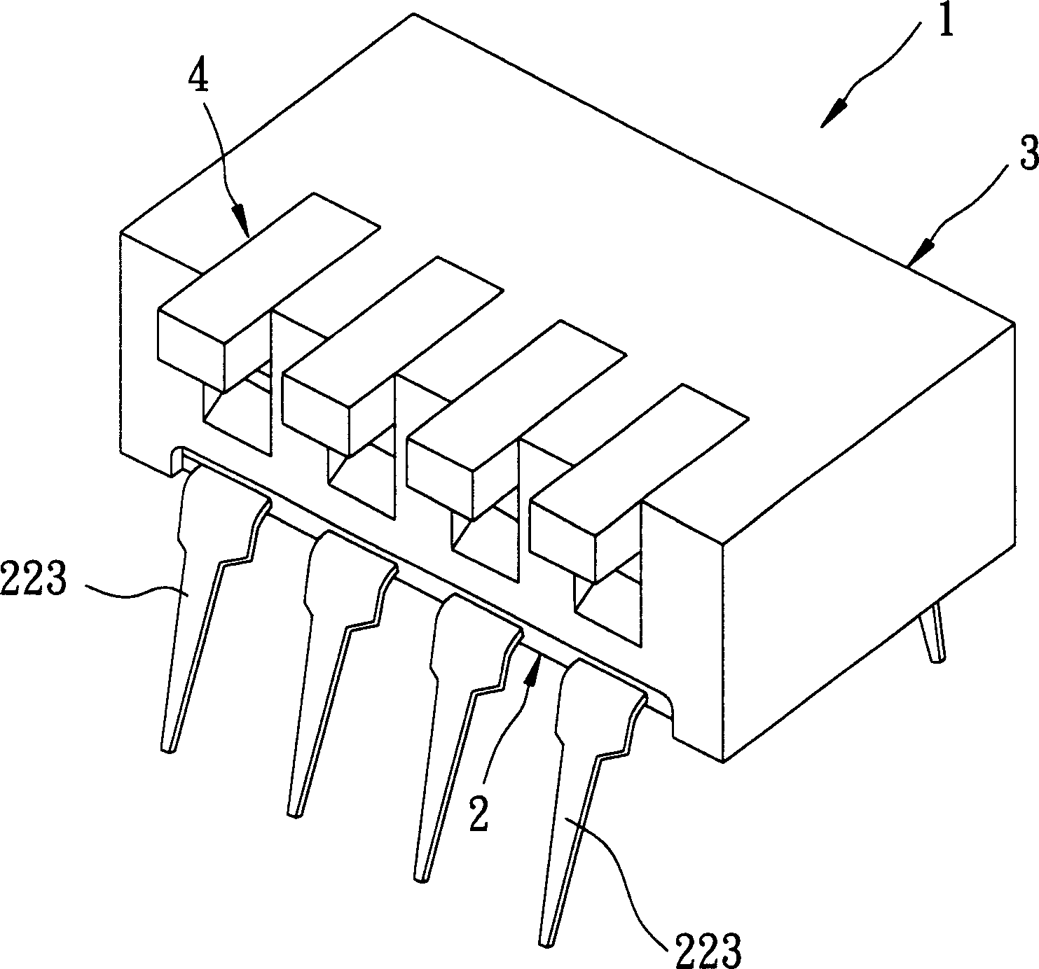
【Technical field】 [0001] The invention relates to a program switch, in particular to a program switch which can be automatically mass-produced by a machine. 【Background technique】 [0002] Such as figure 1 , 2 , 3, the general program switch 1 includes a rectangular base 2, an upper cover 3 that can be sealed on the base 2 and a toggle member 4 that can be pivotally mounted in the upper cover 3 . [0003] The base 2 is made of an insulating material such as rubber or plastic, and its top surface 21 is arranged with several corresponding metal shrapnels 22 along its radial direction, and the peripheral ring of the top surface 21 is provided with a flange 23 , the metal shrapnel 22 are respectively formed with a long shrapnel 221 and a short shrapnel 222, and the long shrapnel 221 are as image 3 It is shown that it is installed under the short elastic pieces 222 and is connected to each other. In addition, the long elastic pieces 221 and the short elastic pieces 222 respec...

Claims


Application Information

Patent Timeline
IPC IPC(8): H01H15/02
Inventor 郭永铭
Owner EXCEL CELL ELECTRONICS
Learn More