Safety adhesive plaster tape packaging cutter driven by handle
A cutter and handle technology, applied in the field of safety tape box sealing cutter, can solve the problems of reducing the efficiency of the tape cutter, reducing the sharpness of the blade, etc., and achieve the effects of large market development prospects, protection and safety, and strong practicability.
- Summary
- Abstract
- Description
- Claims
- Application Information
AI Technical Summary
Problems solved by technology
Method used
Image

Examples
Embodiment 1
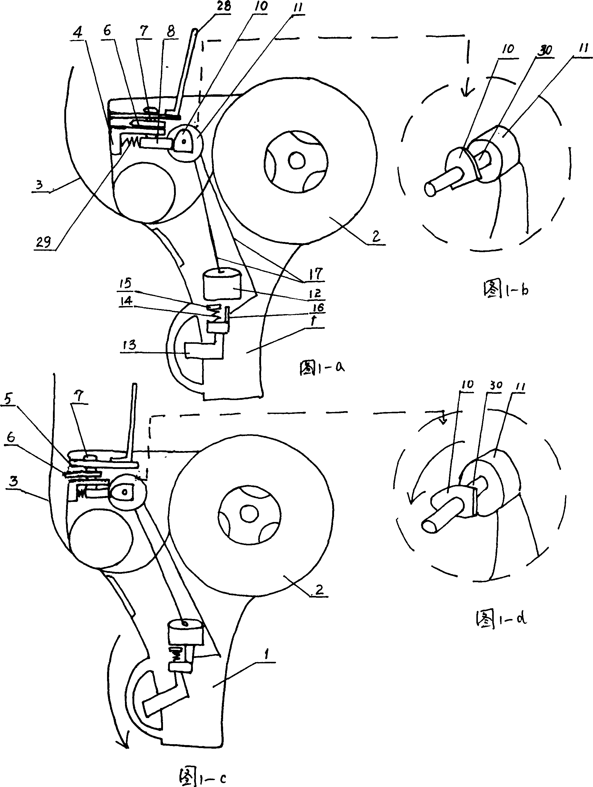
[0022] Embodiment 1: a kind of security tape sealing cutter driven by handle (see figure 1 -a, 1-b, 1-c, 1-d), comprising a handle 1, a tape installation wheel 2 and a tape cutting device with a blade 6, characterized in that at the actuation output of the blade 6 of the cutter is equipped with A control device that controls the access of the blade 6.
[0023] The actuation output end of the blade 6 of the above-mentioned cutter is a similar "F"-shaped blade deriving frame structure; There is a knife edge 5 on the class "F" shaped blade export frame 4, and the blade 6 is installed in the two beams of the class "F" shaped blade export frame 4 according to the sliding shaft 7. The bottom end of the sliding shaft 7 for the blade 6 has a shaft Vertical connection block 8, one end of connection block 8 is connected with the output end of power take-off device, and the other end of connection block 8 is connected with class " F " shape blade derivation frame 4 by fixed spring 29 (s...
Embodiment 2
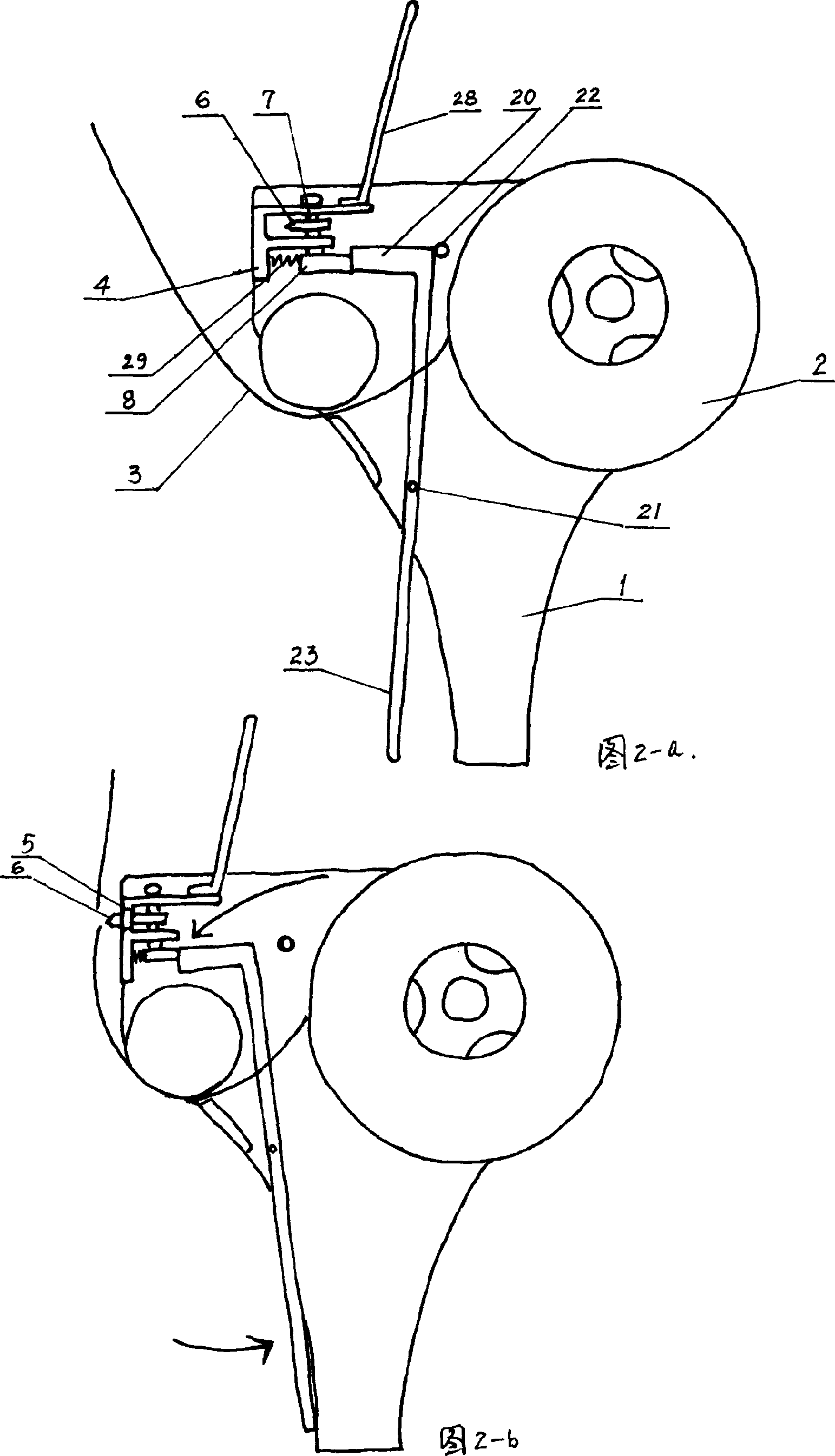
[0026] Embodiment 2: a kind of security tape sealing cutter driven by handle (see figure 2 -a, 2-b) It includes a handle 1, a tape installation wheel 2 and a tape cutting device with a blade 6, which is characterized in that a control device for controlling the entry and exit of the blade 6 is installed at the actuation output end of the blade 6 of the cutter.
[0027]The actuation output end of the blade 6 of the above-mentioned cutter is a similar "F"-shaped blade deriving frame structure; There is a knife edge 5 on the class "F" shaped blade export frame 4, and the blade 6 is installed in the two beams of the class "F" shaped blade export frame 4 according to the sliding shaft 7. The bottom end of the sliding shaft 7 for the blade 6 has a shaft Vertical connection block 8, one end of connection block 8 is connected with the output end of power take-off device, and the other end of connection block 8 is connected with class " F " shape blade derivation frame 4 by fixed spri...
Embodiment 3
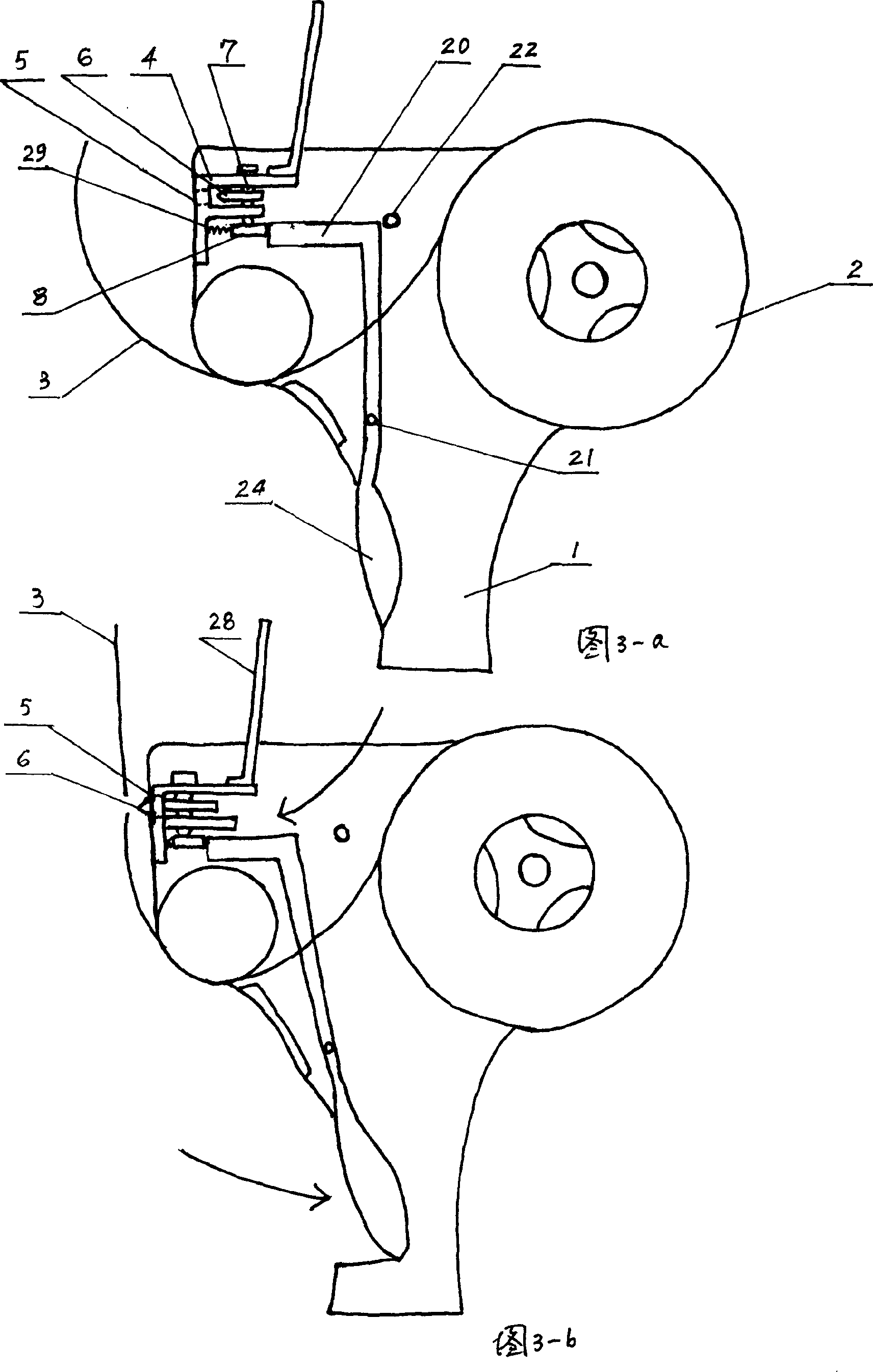
[0031] Embodiment 3: a kind of safety tape sealing cutter driven by handle (see image 3 -a, 3-b), including a handle 1, tape installation wheel 2 and a tape cutting device with a blade 6, characterized in that a control device for controlling the entry and exit of the blade 6 is installed at the actuating output end of the blade 6 of the cutter.
[0032] The actuation output end of the blade 6 of the above-mentioned cutter may be an "F"-shaped blade lead-out frame structure.
[0033] The above-mentioned power output device in the control device of the control blade 6 that is equipped with at the blade actuating output end of the cutter adopts class " 7 " shape lever 20 driving devices (same as example 2).
[0034] The bottom of the above-mentioned class "7" shape lever 20 is a trigger-shaped trigger 24 relative to the handle 1.
[0035] A transparent baffle structure 28 covering the blade can be installed above the blade actuating output end of the above-mentioned cutter.
PUM
 Abstract
Description
Claims
Application Information
PatSnap Eureka turns technology decisions into work you can execute. Powered by our Innovation Knowledge Graph, it runs expert workflows across engineering, life sciences, materials and intellectual property. Get your review-ready output in minutes.


