Air intake arrangement of isolating chamber

A technology of vacuum isolation chamber and air intake structure, which is applied in electrical components, semiconductor/solid-state device manufacturing, circuits, etc., can solve the problems of affecting the quality of the wafer, easy to generate turbulence, and increase the ventilation time, so as to improve the output and pass rate. Effect

Inactive Publication Date: 2003-12-31
MACRONIX INT CO LTD
View PDF0 Cites 8 Cited by
  • Summary
  • Abstract
  • Description
  • Claims
  • Application Information

AI Technical Summary

Problems solved by technology

When the vacuum isolation chamber 30 is vacuum broken, the slow ventilation line (adjustment valve 332+pneumatic valve 331) must first be used for slow ventilation, and the fast ventilation line should be started after the pressure is greater than a certain value (200 Torr). (Pneumatic valve 333) performs full-flow ventilation, so the ventilation time will increase, increasing the production time of a single wafer; on the other hand, the control method of the gas flow controller 33 is more complicated and requires higher pipeline costs.
[0006] Additionally, if figure 1 and figure 2 As shown, there is a ventilation port at the bottom of the vacuum isolation chamber 30, and a particle filter device 32 is provided at the outlet. Faster, very easy to produce turbulent flow, and there is a wafer carrier 31 below the vacuum isolation chamber 30, which is also easy to cause the inflowing gas to generate turbulent flow, so that the particles deposited on the bottom of the vacuum isolation chamber 30 due to the influence of gravity are lifted up, affecting wafer quality

Method used


Image

  • Air intake arrangement of isolating chamber
  • Air intake arrangement of isolating chamber
  • Air intake arrangement of isolating chamber

Examples


Embodiment Construction

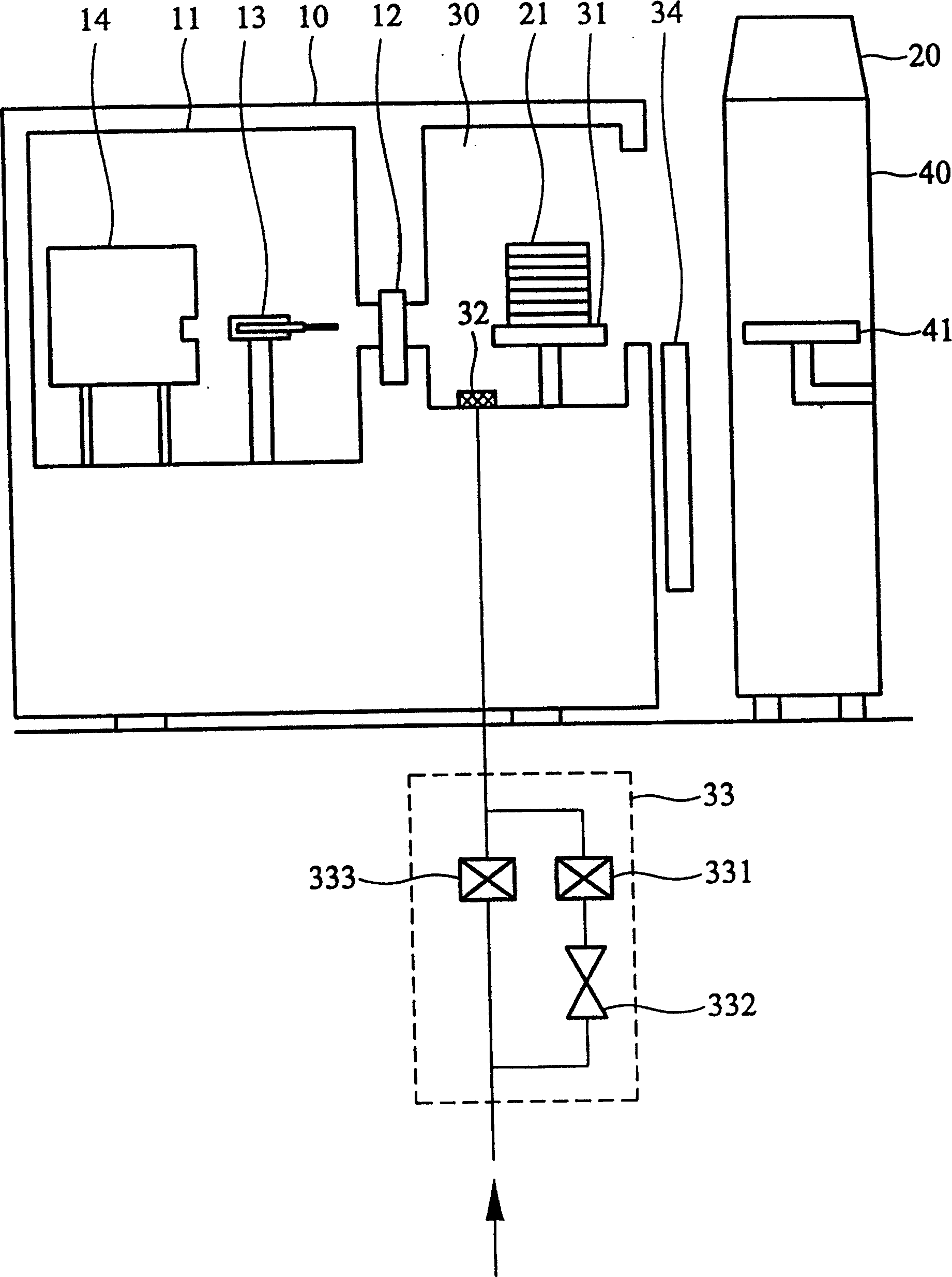
[0028] Figure 4 It is a schematic diagram of the ventilation device for the vacuum isolation chamber 30 of the semiconductor machine according to the embodiment of the present invention. Such as Figure 4 As shown, in the wafer factory, the wafer boat 20 is placed on the SMIF interface 40 by the on-line staff or the unmanned transport vehicle, and the wafer 21 is transferred from the wafer boat 20 to the semiconductor machine 10 by the robot arm of the SMIF interface 40 In the vacuum isolation chamber 30 of the vacuum isolation chamber 30, the dodge door 34 is closed and the vacuum isolation chamber 30 is airtight at this moment. Since semiconductor equipment must be in a vacuum state when producing wafers, the vacuum isolation chamber 30 must be continuously switched between vacuum and atmospheric pressure. In the embodiment of the present invention, the original gas flow controller is changed to a new control valve 50, and only a single vent valve 51 is used to control th...


PUM


Abstract

An gas-input structure for load lock chamber of semi-conductor device, comprising, a filtration device arranged on the top of the load lock chamber, a pressure limiting device connected with nitrogen gas source; and a ventilating device connected with the pressure device and the filtration device via pipeline, in which the ventilating device is a ventilating valve, the ventilating valve can be controlled as the load lock chamber is just in the vacuum state, and can introduce the gas from gas source with the maximum ventilation flow into the load lock chamber, so that the time for wafer to carry chamber broken vacuum is reduced, and output of machine desk is increased.

Description

technical field [0001] The invention relates to a vacuum isolation chamber, in particular to a vacuum isolation chamber of a semiconductor device. Background technique [0002] In the semiconductor manufacturing process, wafers often need to be processed in a vacuum state due to the relationship between the manufacturing process, so the semiconductor machine tool must continuously perform pressure conversion between vacuum and atmospheric pressure. In order to keep the reaction area in the machine in a stable state, an isolation chamber connected to the outside clean room is usually set inside the semiconductor machine to place the standard mechanical interface (SMIF interface for short). ) the incoming wafer, or the wafer that has been processed in the reaction chamber, and the pressure conversion between the vacuum and an atmospheric pressure is carried out in this isolation chamber, and this isolation chamber is generally called a vacuum isolation chamber (Load LockChambe...

Claims


Application Information

Patent Timeline
Patent Type & Authority Applications(China)
IPC IPC(8): H01L21/00
Inventor 施世濠陈委辰罗际诚刘信成林育安
Owner MACRONIX INT CO LTD
Why Eureka
Try Eureka