Flow control valve

A technology of flow control valve and fluid flow, applied in flow control without auxiliary power, safety valve, balance valve, etc., can solve the problems of complex mechanism, complex manufacturing method, lack of repeatability, etc., and achieve the effect of simple mechanism

Inactive Publication Date: 2004-01-07
HATTERSLEY NEWMAN HENDER
View PDF2 Cites 10 Cited by
  • Summary
  • Abstract
  • Description
  • Claims
  • Application Information

AI Technical Summary

Problems solved by technology

[0006] There are several problems with this structure: First, for low and very low flows, the Reynolds number is the Reynolds number in laminar or transition state flow whi

Method used


Image

  • Flow control valve
  • Flow control valve
  • Flow control valve

Examples


Embodiment approach

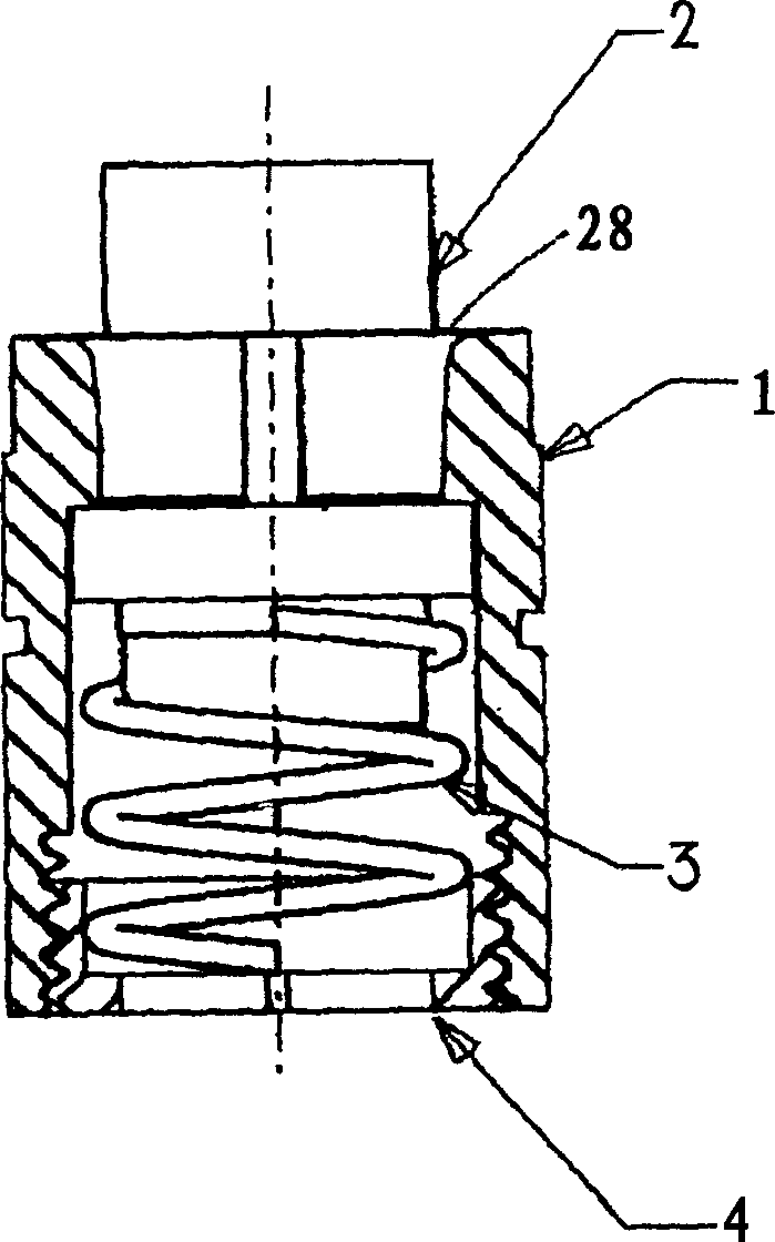
[0036] The constant flow valve is formed in the form of a cartridge which, in use, is mounted within a housing (not shown). The valve comprises a body part 1 , a piston part 2 , a compression spring 3 and a bottom ring 4 . The dimensions of these components can be varied to provide different predetermined fluid flow rates, and the housing can be fitted with a range of different cartridges depending on the required flow rates.

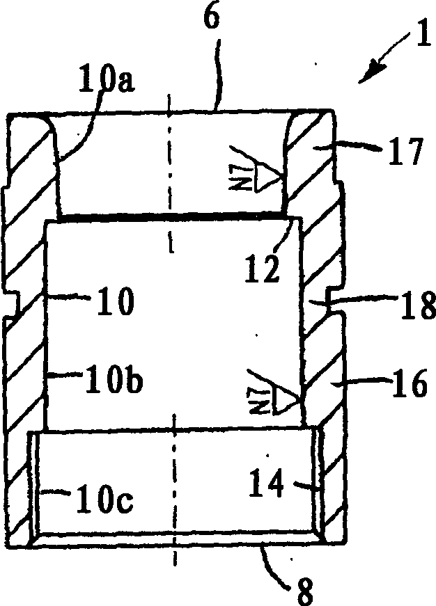
[0037] The main body 1 is substantially cylindrical with an inlet end 6 and an outlet end 8 . An axial bore 10 defining a fluid flow passage extends longitudinally through the body, the bore comprising an upper portion 10a, a middle portion 10b and a lower portion 10c.

[0038] The diameter of the upper part 10 a of the hole is non-uniform, increasing towards the inlet end 6 . The upper portion is flared or flared, and in the embodiment shown its diameter increases from about 13 mm at the lower end to about 15 mm at the inlet end. The shape of the fl...


PUM


Abstract

The valve includes the body part and the elastic piston part with bias pressure being added to. The body part has a hole defining the fluid flow channel. The piston part installed in the said channelcan be moved to the body part relatively in order to respond to the difference of fluid pressure across the valve. The piston part defines the annular theittling orifice between the piston part and the hole. The part of the channel possesses a non-homogeneous profile. Thus, the size of the annular orifice is dependent on the related position between the piston part and the body part.

Description

technical field [0001] The present invention relates to a flow control valve that delivers a substantially constant flow of fluid regardless of the pressure differential across the valve. Background technique [0002] For convenience, the invention will be described with particular reference to valves in recirculating hot water radiators for central heating systems, but it should be understood that its use is not limited thereto, and in fact it is generally used extensively in in the fluid system. [0003] In large central heating systems such as in multi-storey office buildings, calibration valves are often used in practice to balance the distribution of fluids. A mains loop keeps hot water pumped from a boiler, usually located in the basement, to the top floor and cycled back and forth. In each level, a secondary duct loop is directly connected to the main loop and feeds a series of radiators connected between the supply and return ducts of the secondary loop. You can a...

Claims


Application Information

Patent Timeline
IPC IPC(8): F16K17/22G05D7/01
Inventor 约翰·H·梅
Owner HATTERSLEY NEWMAN HENDER
Why Eureka
Try Eureka