Fishing reel braring and component support structure
A supporting structure and reel technology, which is applied to fishing reels, bearing components, shafts and bearings, etc., and can solve problems such as bearings that cannot be cleaned, and internal parts of the reel that are eroded and corroded
- Summary
- Abstract
- Description
- Claims
- Application Information
AI Technical Summary
Problems solved by technology
Method used
Image

Examples
no. 1 example
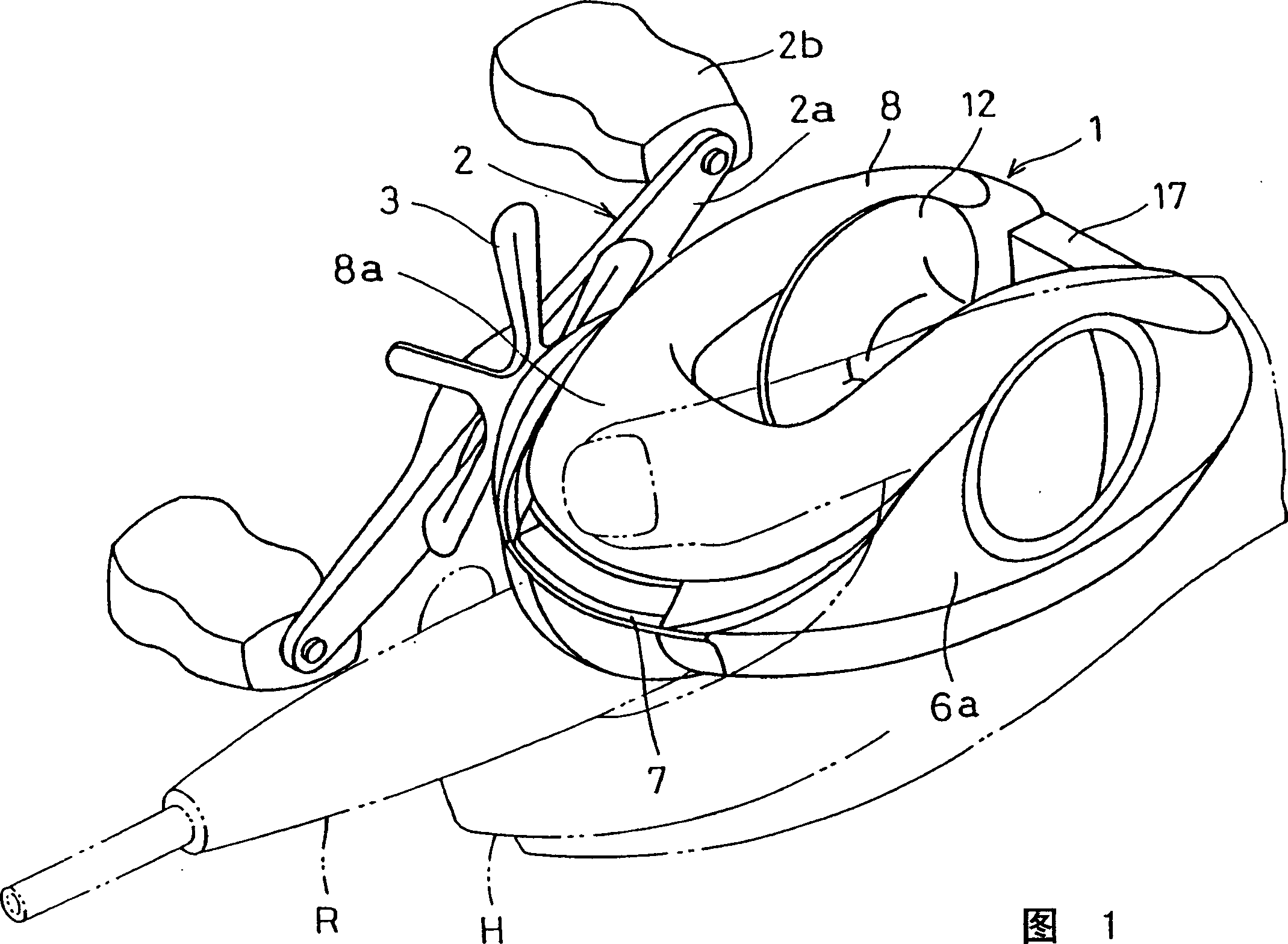
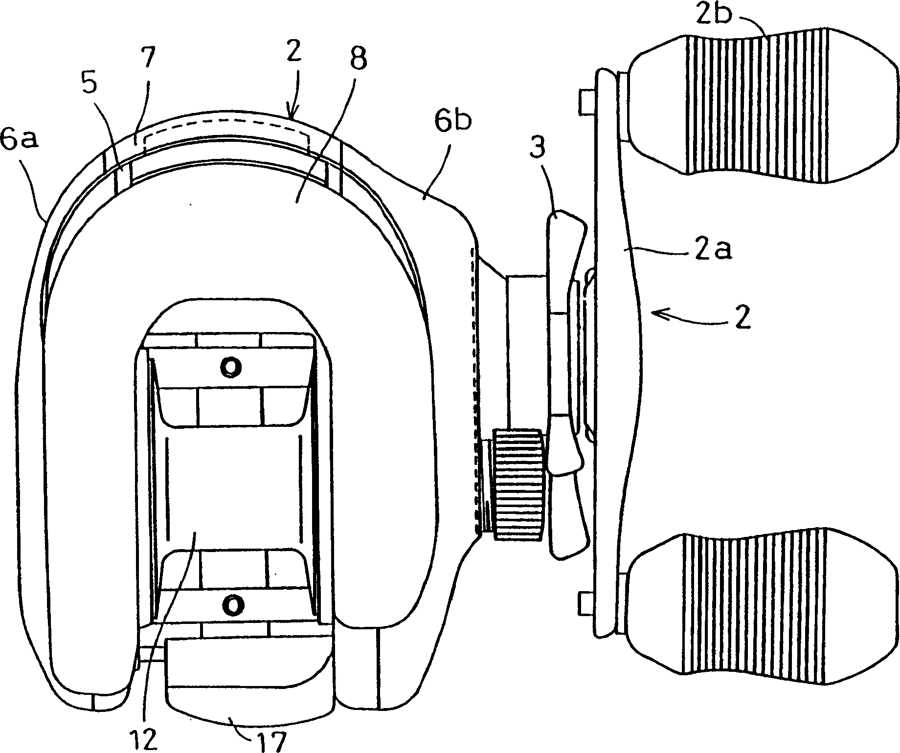
[0031] Figure 1 and figure 2 As shown, a dual bearing reel suitable for one embodiment of the present invention is a streamlined reel for casting fishing. This reel is equipped with a reel body 1; a reel crank handle 2 disposed on the side of the reel body 1; 1 and the fishing line reel 12 removed therefrom. A claw 3 for adjusting the tension on the reel 12 is provided on the side of the handle 2 of the reel body 1 .
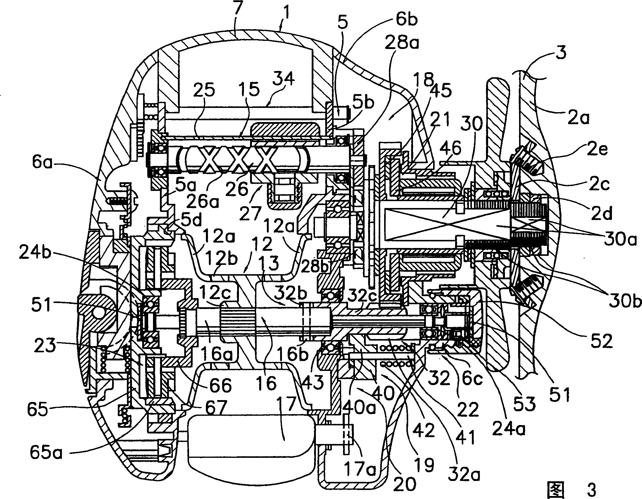
[0032] The handle 2 is in the form of a double handle having a plate-shaped handle arm 2a and grips 2b mounted freely rotatable on both ends of the handle arm 2a. As shown in FIG. 3, the arm 2a is fixed by two screws 2e to a washer 2c non-rotatably fixed to the tip of the handle shaft 30 by a nut 2d. A nut 2d is accommodated inside the handle arm 2a and is prevented from rotating by it. Therefore, this configuration allows the outer surface of the arm 2a to be a seamless smooth surface, which means that the structure of the arm 2a is not easily entangled wit...
no. 2 example
[0066] In the aforementioned first embodiment, an example was given by taking a double-bearing reel as the fishing reel, but the present invention can be applied to other fishing reels such as spinning reels.
[0067] In FIG. 8 , a spinning reel employing an embodiment of the present invention is equipped with a handle 101 , a reel unit 102 rotatably supporting the handle 101 , a rotor 103 and a spool 104 . The rotor 103 is rotatably supported at the front of the reel unit 102 . The spool 104 around which the fishing line is wound is arranged so as to move back and forth in front of the rotor 103 .
[0068] As shown in Figure 8, Figure 9 As shown, the handle 101 includes a T-shaped grip portion 101a, an L-shaped crank arm 101b rotatably fitted on the tip end of the grip portion 101a, and a shaft portion 101c fitted at the base end of the crank arm 101b. The crank arm 101b is bendable at the base end by a single touch. Such as Figure 9 As shown, the shaft portion 101c is ...
no. 3 Embodiment
[0088] exist Figure 11 Among them, the drag reel adopting the third embodiment of the present invention includes a tubular reel unit 201, a spool shaft 202 mounted in the center of the reel unit 201 axially movable but non-rotatable, free to rotate but not rotatable The spool 203 is installed on the spool shaft 202 so as to move axially, and the handle 204 is arranged on the side of the reel unit 201 . Inside the reel unit 201 , the drag reel is also equipped with a drag mechanism 207 that transmits the rotation of the handle 204 to a gear mechanism 206 on the spool 203 and brakes the spool 203 .
[0089] The reel unit 201 has a disc-shaped side plate 210 and a reel body 211 coaxially connected to the side plate 210 through a sleeve joint and fixed by screws. The ends of the spool shaft 202 are supported approximately in the center by side plates 210 so that they are non-rotatable but axially movable. An interlocking groove 210b is formed in the center hole, and an interloc...
PUM
 Abstract
Description
Claims
Application Information