Manufacture of miniature industrial fuse

A manufacturing method and technology of fuses, applied in the manufacture of fuses, etc., can solve problems such as difficulty in fixing fuses 21, difficulty in soldering, failure of products to meet requirements, etc., and achieve the effect of improving the rate of high-quality products and stability, and low impedance value

Inactive Publication Date: 2004-01-21
邱鸿智
View PDF0 Cites 5 Cited by
  • Summary
  • Abstract
  • Description
  • Claims
  • Application Information

AI Technical Summary

Problems solved by technology

[0003] In the general manufacturing method, when the fuse 21 is welded on the two sets of joints 20, it is often difficult to position the fuse 21 before welding because there is no proper positioning design on the two sets of joints 20, which affects the welding work. The assembly part 20 is not designed with any structure that helps the solder to adhere, which often makes it difficult for the solder to adhere, and it is also difficult to fix the fuse 21, resulting in many products that cannot meet the requirements, and the rate of good products is low, because the amount of solder adhered The amount directly affects the impedance value of the product

Method used


Image

  • Manufacture of miniature industrial fuse
  • Manufacture of miniature industrial fuse
  • Manufacture of miniature industrial fuse

Examples


Embodiment Construction

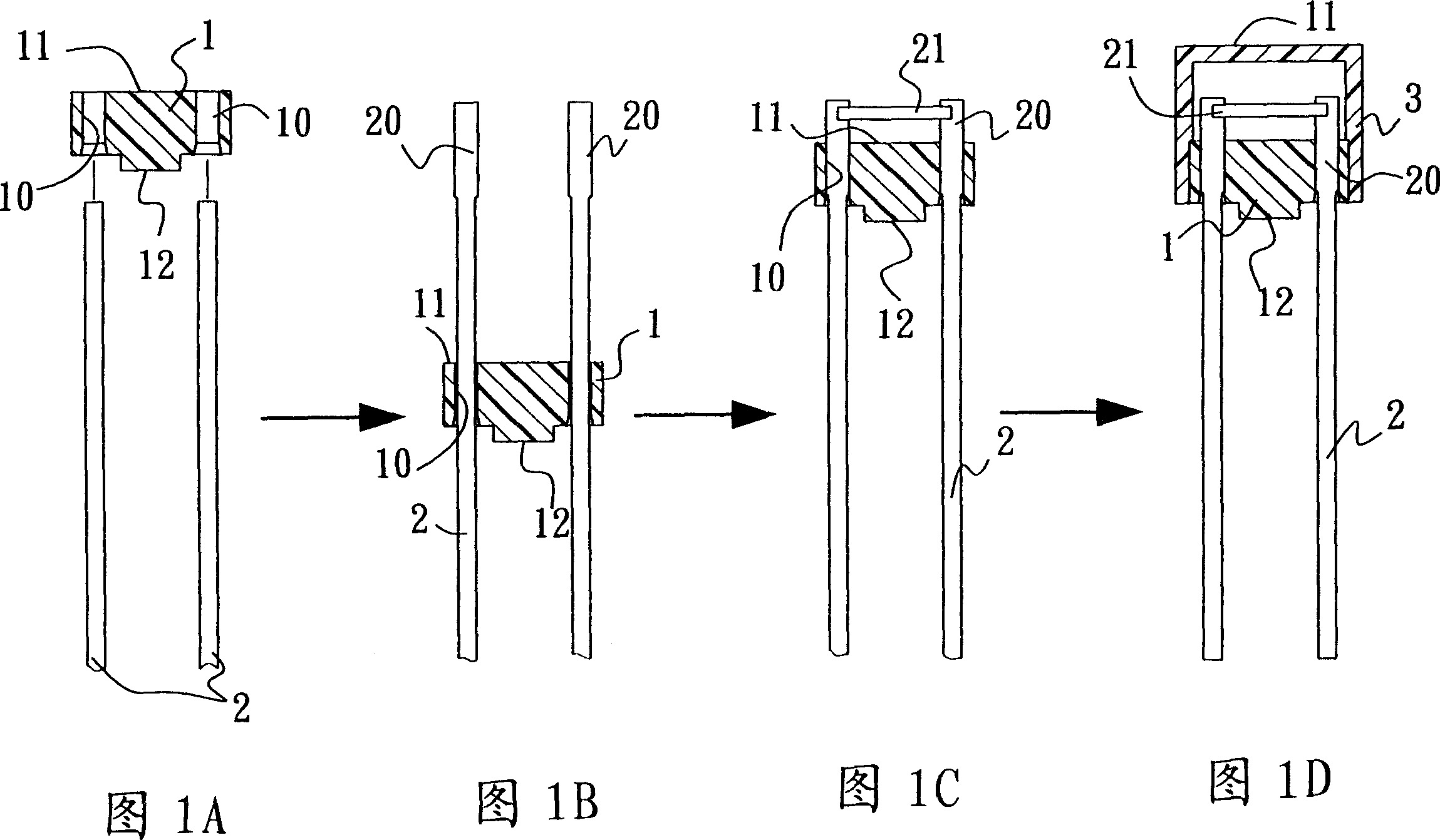
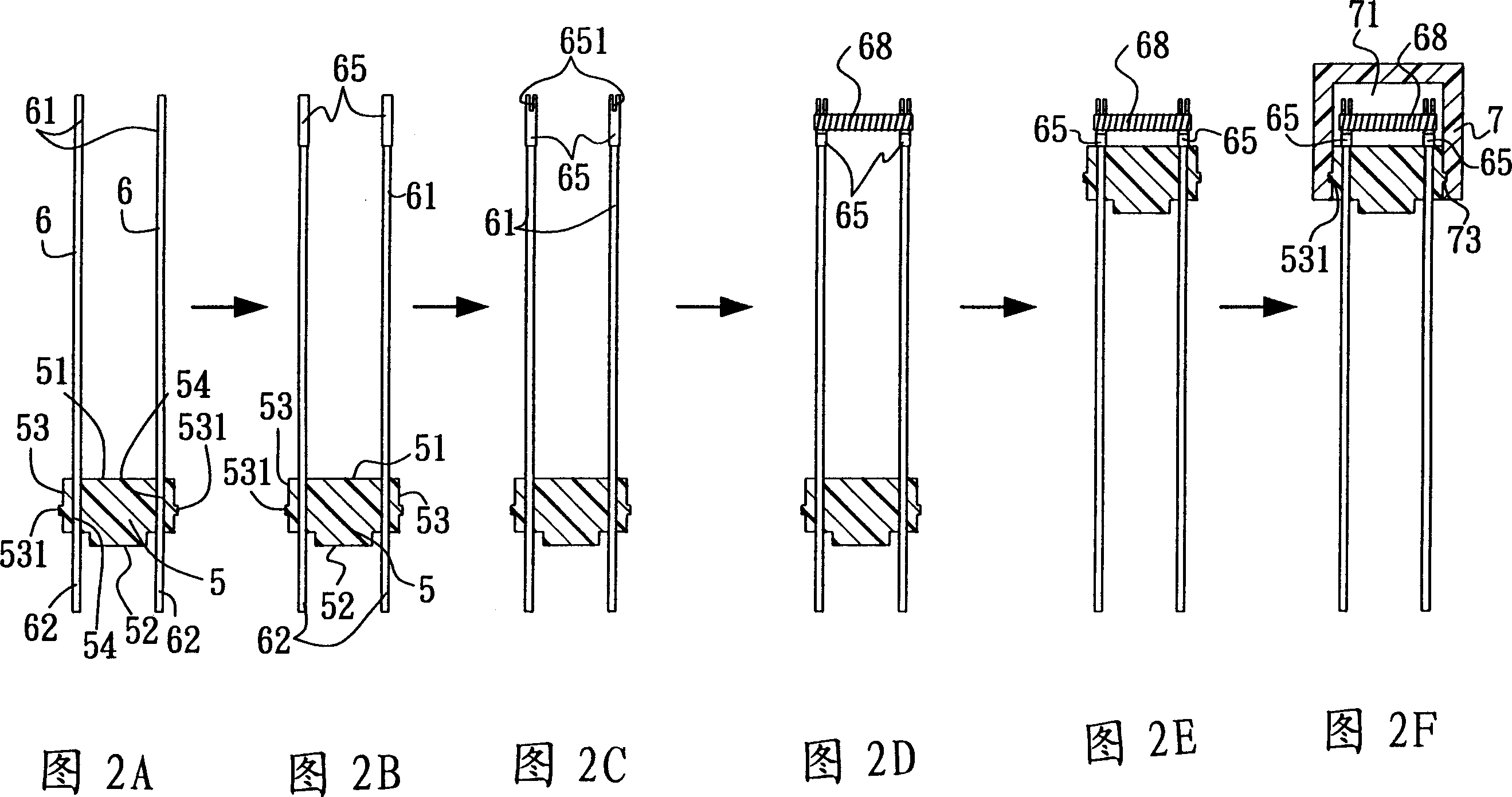
[0021] As shown in Figures 2A-2F, it is a better embodiment of the manufacturing method of the industrial micro-fuse of the present invention. In step a of this embodiment, a base body 5 is injection-molded first, and the base body 5 is a cylinder with a first surface. 51. A second face 52 that is opposite to the first face 51, and a side edge 53 that is arranged on the first face 51 and the second face 52, and a flange 531 is arranged on the side edge 53, and is placed on the seat The body 5 is provided with two parallel perforations 54 penetrating through the first and second surfaces 51 , 52 .

[0022] In step b, a wire 6 is respectively pierced on the two through holes 54. The two wires 6 are arranged in parallel with equal lengths, and both have a first end 61 and a second end 62 opposite to the first end 61. The two wires 6 The first and second ends 61 and 62 are located on both sides of the first and second surfaces 51 and 52 of the seat body 5 respectively, so that the...


PUM


Abstract

The manufacture of miniature industrial fuse includes the following steps: forming fuse seat with two parallel holes; threading two wires with connecting part in the same side of the fuse seat through the two holes; flattening the connecting parts, cutting notches and forming curved slots; welding one fuse onto the curved slots; and covering the seat with one cover to cover the two connecting parts and the fuse. Welding in the connecting parts results in stable connection and high product quality.

Description

【Technical field】 [0001] The invention relates to a method for manufacturing an industrial micro-fuse, in particular to a method for manufacturing an industrial micro-fuse that allows solder to adhere more effectively and securely weld the fuse. 【Background technique】 [0002] As shown in Figures 1A-1D, the general micro-fuse is made by forming a base 1 first, the base 1 has a first surface 11 and a second surface 12 opposite to the first surface 11, and on the first surface 11 There are two through holes 10 running through the second surface 12 . Pass the two wires 2 through the above-mentioned through hole 10 respectively, and make both ends of the two wires 2 protrude from the first surface 11 and the second surface 12 of the base 1 by a proper length. A set of joints 20 are respectively formed at one end of the two wires 2 located on the first surface 11 of the base 1, and the two sets of joints 20 are pressed into a flat shape on the same plane, and a fuse 21 is welded...

Claims


Application Information

Patent Timeline
Patent Type & Authority Applications(China)
IPC IPC(8): H01H69/02
Inventor 邱鸿智
Owner 邱鸿智
Why Eureka
Try Eureka