

Whole forming method for cylindrical netting support with horizontal sliding structure
A technology of cylindrical reticulated shell and integral forming, which is applied in the direction of building structure and construction, can solve the problems of prominent safety hazards of temporary load-bearing supports, large amount of temporary support scaffolding, prominent stability problems of jacking devices, etc., and achieve control work Convenience, safety and reliability, good construction quality and convenient control
- Summary
- Abstract
- Description
- Claims
- Application Information
AI Technical Summary
Problems solved by technology
Method used
Image

Examples
Embodiment 1
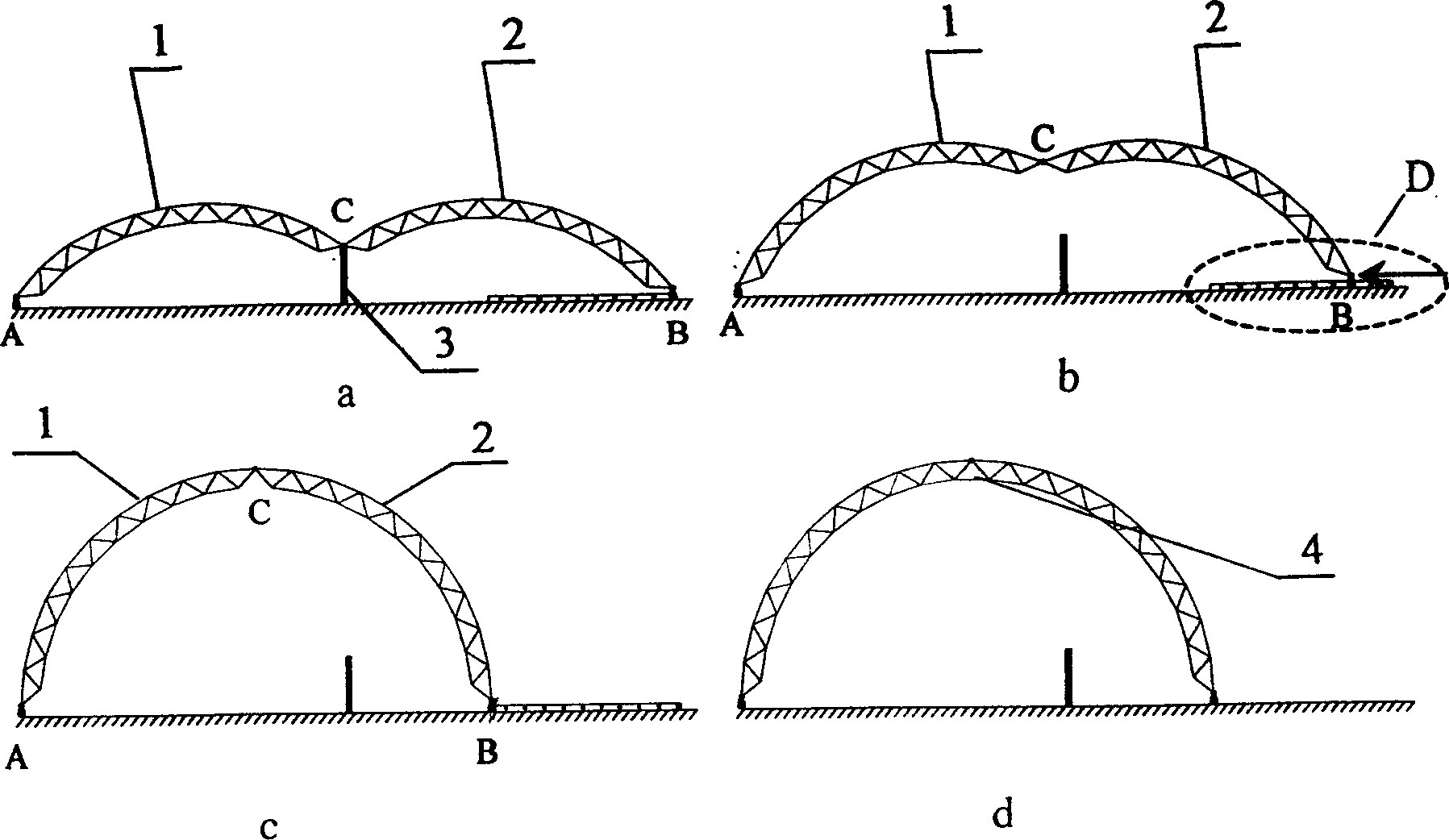
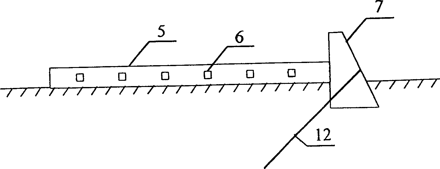
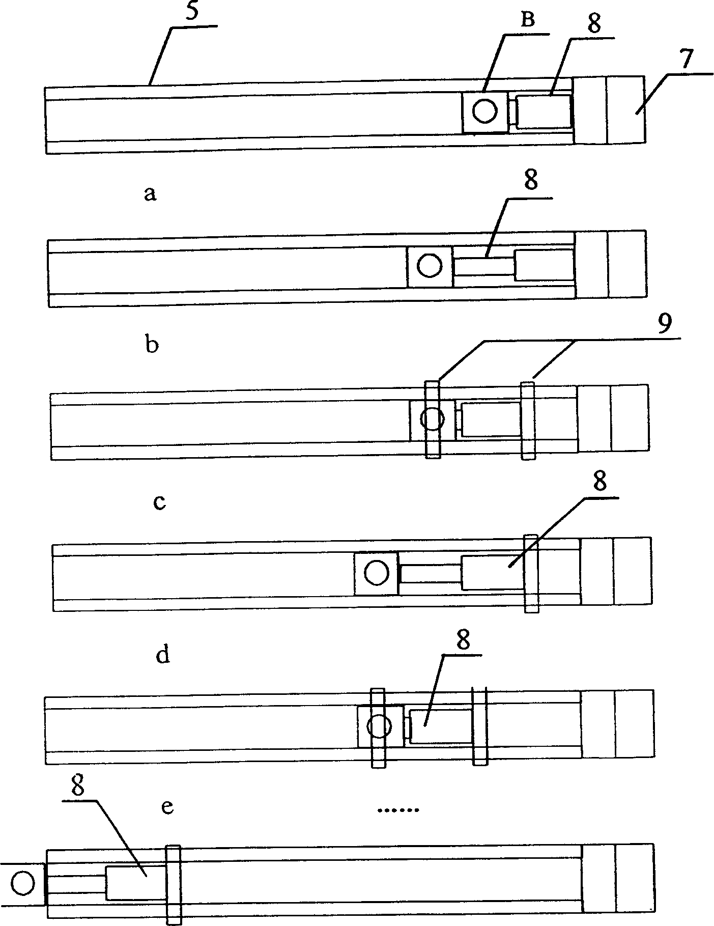
[0019] like figure 1 , figure 2 , image 3 Shown is the jack push support method. The hinge support B is placed in the grooved slideway 5. There are several positioning holes 6 on the side of the grooved slideway 5. A bearing is tightly installed on the outer surface of the grooved slideway 5. The force base 7, the load base 7 is inserted into the soil anchor rod 12 to strengthen the fixing effect, and the jack 8 is installed between the load base 7 and the sliding hinge support B, and the sliding hinge support B is under the horizontal external force of the jack 8 during construction Carry out horizontal push movement in sections in the direction of the fixed hinge support A. When the jack 8 reaches the limit position, use the load-bearing channel steel 9 to penetrate into the positioning hole 6, respectively fix the sliding hinge support B and the jack 8, and then loosen them. Sliding hinge support B, continue to push the jack 8 until it reaches the design position of sli...
Embodiment 2
[0021] like figure 1 , Figure 4 , Figure 5 Shown is the through-the-center jack traction support method, the other end point of which is the sliding hinge support B placed in the groove-shaped slideway 5, and the inner side of the groove-shaped slideway 5 is equipped with a load-bearing pedestal 7, bearing The force pedestal 7 is inserted into the soil anchor rod 12 to strengthen the fixing effect, and the outer surface of the force pedestal 7 is equipped with a through-type jack 11, and the through-type jack 11 is connected with the sliding hinge support B with a steel strand 10, and slides during construction. Under the action of the horizontal external force of the through-hole jack 11, the hinge support B is continuously pulled in the direction of the fixed hinge support A through the steel strand 10 until it reaches the design position of the slide hinge support B.
Embodiment 3
[0023] like figure 1 , Image 6 , Figure 7 Shown is the traction sliding hinge support method of the fixed hinge support of the through-hole jack, and the other end point is the sliding hinge support B which is placed in the groove-shaped slideway 5, and the through-hole jack 11 is placed on the fixed hinge support. One side of the seat A, one side of the steel strand 10 passes through the node of the fixed hinge support A and is connected with the through-hole jack 11, and the other side of the steel strand 10 is connected with the sliding hinge support B, and slides during construction. Under the action of the horizontal traction force of the through-hole jack 11, the hinge support B continuously moves horizontally towards the fixed hinge support A through the steel strand 10 until it reaches the design position of the slide hinge support B.
PUM
 Abstract
Description
Claims
Application Information