
High-frequency heater

A technology of high-frequency heating device and rectifying device, which is applied in microwave heating and other directions

Inactive Publication Date: 2004-02-04
DELTA ELECTRONICS INC
View PDF0 Cites 1 Cited by
  • Summary
  • Abstract
  • Description
  • Claims
  • Application Information

AI Technical Summary

Problems solved by technology

[0014] Another object of the present invention is to provide a magnetron high-frequency heating device to solve the problem of the input current ripple and the bias value of the transformer in the circuit, and improve the power factor (PowerFactor) and efficiency

Method used


Image

  • High-frequency heater
  • High-frequency heater
  • High-frequency heater

Examples


Embodiment Construction

[0052] see Figure 6 , is a schematic circuit diagram of a current-mode regulating transformer DC-DC converter (DC / DC Converter) in the first preferred embodiment of the present invention, that is, a CTT (Current Tapping Transformer) DC / DC converter. Such as Figure 6 As shown, a high-frequency heating device 200 includes: a filter inductor 201, a center-tapped transformer 202, a filter capacitor 203, a first switch 204, and a series circuit including a second switch 205 and a first switch 205 connected in series. Two capacitors 206 , a first capacitor 207 , a rectifier 208 and a magnetron 209 . The filter inductor 201 is connected to a DC power supply V dc A positive terminal (+). The center tap transformer 202 includes a center tap end, a first end and a second end, and the center tap end is connected to the other end of the filter inductor 201 . The filter capacitor 203 has one end connected to the first end of the center-tapped transformer 202, and the other end connec...


PUM


Abstract

The present invention provides a high-frequency heating apparatus, comprising a filtering inductor connected to a positive end of a D.C. power supply; an intermediating tap transformer including a first end and a second end, the intermediating tap connected to the other end of the filtering inductor; a filtering capacitor, one end of it connected to the first end of the intermediating tap transformer, and the other end of it connected to the negative end of the D.C. power supply; a first switch which connects the second end of the intermediating tap transformer and the negative end of the D.C. power supply in series; a series circuit including a second switch and a second capacitor in series and connected to the intermediating tap transformer; a first capacitor connected to the intermediating tap transformer.

Description

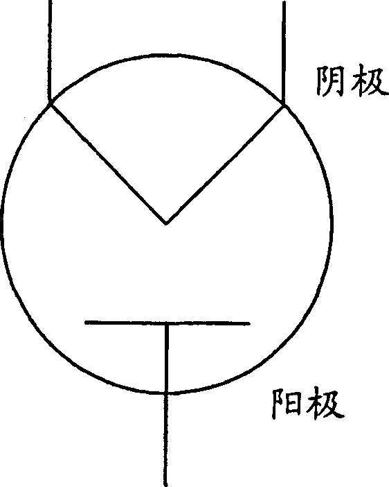
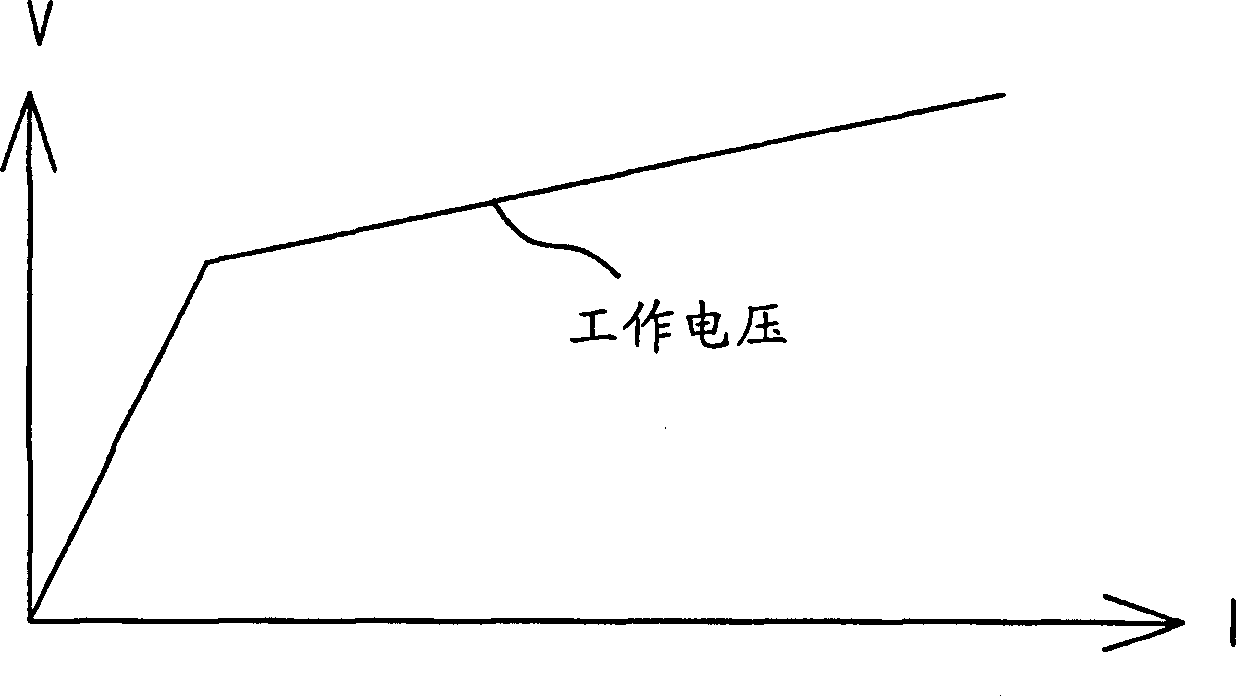
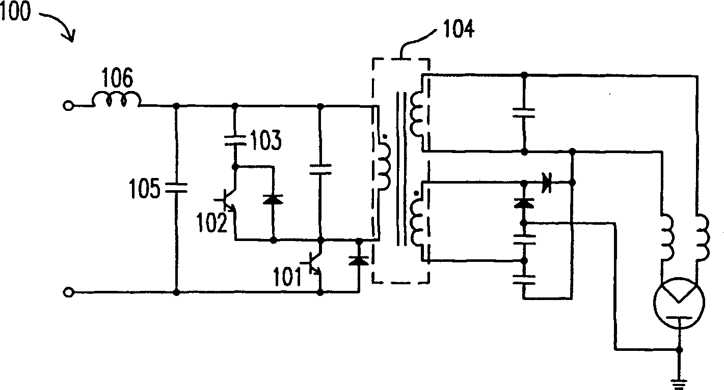
(1) Technical field [0001] The invention relates to a high-frequency heating device applied to a magnetron. (2) Background technology [0002] figure 1 It is a schematic diagram of a conventional magnetron (magnetron) circuit. Such as figure 1 As shown, a magnetron is a vacuum tube used to generate microwaves. The condition for its normal operation is: when the cathode temperature exceeds 2100K (absolute temperature), a negative high voltage (thousands of thousands) is applied between the cathode and the anode. volt). However, different magnetrons have different operating voltages, but their voltage and current characteristic curves are basically similar, such as figure 2 shown. When the voltage between the cathode and the anode reaches the operating voltage, the magnetron generates a microwave, and the voltage between the cathode and the anode is clamped near the operating voltage. At this time, the characteristics of the magnetron are quite In a regulator tube. [...

Claims


Application Information

Patent Timeline
IPC IPC(8): H05B6/66
Inventor 应建平郭兴宽曾剑鸿
Owner DELTA ELECTRONICS INC
Learn More