Judging method for heavy saturation of current transformer by time-difference method for relay protection

A current transformer and relay protection technology, applied in the field of power system fault judgment, can solve the problems of not being able to identify current transformer saturation, affecting the reliability of differential protection, etc., to achieve the effect of improving reliability

Active Publication Date: 2004-02-11
NANJING GUODIAN NANZI POWER GRID AUTOMATION CO LTD
View PDF0 Cites 25 Cited by
  • Summary
  • Abstract
  • Description
  • Claims
  • Application Information

AI Technical Summary

Problems solved by technology

However, if the saturation of the current transformer is serious, it occurs before 1/4 cycle, and even the saturation time is as small as 2ms. At this time, there are few data used as the differential criterion of relay protection, which will inevitably affect

Method used


Image

  • Judging method for heavy saturation of current transformer by time-difference method for relay protection
  • Judging method for heavy saturation of current transformer by time-difference method for relay protection
  • Judging method for heavy saturation of current transformer by time-difference method for relay protection

Examples


Embodiment Construction

[0036] The present invention will be further described below in conjunction with the accompanying drawings and embodiments.

[0037] A method for judging severe saturation of current transformers using time-difference method for relay protection, the judging process is as follows:

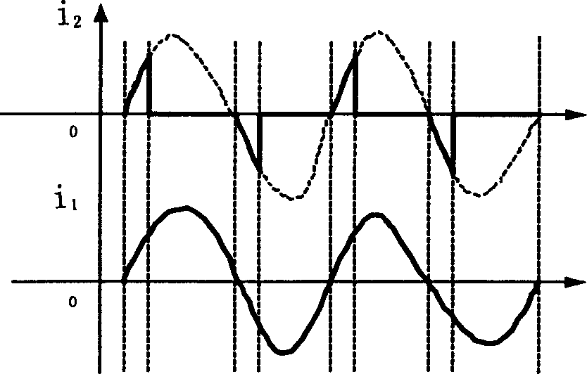
[0038] a. Divide each current cycle into N sampling points, collect the secondary current of the current transformer on both sides of the protected component, and perform analog-to-digital conversion to obtain the current i of each sampling point 1p , i 2p (p=0, 1, . . . , N-1). Set the two sides of the protected element as the non-polarity end, i 1 Indicates the sum of the secondary currents of each current transformer of the input sampling current on one side of the protection element, i 2 Indicates the sum of the secondary currents of each current transformer for the output sampling current on the other side of the protected element.

[0039] b. Calculate the differential current i before th...


PUM


Abstract

This invention discloses a method for judging current mutual inductor heavy saturation with a time difference method for relay protection which can distinguish heavy saturation. Since the saturated point at CT saturation separates a second current into unsaturated zone and saturated zone, relations of their differential current and stalling current are different, it can identify the heavy CT saturation when saturation time reaches to 2ms. CT saturation arisen from faults in or out of the zone can be distinguished using the time difference method.

Description

technical field [0001] The invention belongs to the fault judgment of power system. In the protection of low-voltage, high-voltage, ultra-high-voltage and ultra-high-voltage power equipment in the power system, the reliability of differential protection is increased by using the saturation criterion of current transformer (CT), which is a high-reliability The time-difference method is used to judge the severe saturation of the current transformer for relay protection with sensitivity. Background technique [0002] With the development of the power system, the capacity of the power system increases, and the short-circuit capacity of the existing primary equipment such as the current transformer increases, which requires higher requirements for the transient characteristics of the current transformer. It is very easy to saturate under the condition of short circuit current. [0003] As the relay protection for protecting power system equipment, the quantity based on it is tak...

Claims


Application Information

Patent Timeline
IPC IPC(8): H02H3/26
Inventor 赵永彬
Owner NANJING GUODIAN NANZI POWER GRID AUTOMATION CO LTD
Why Eureka
Try Eureka