
Directional microphone

A directional microphone and microphone technology, which can be applied to sensors, microphone signal combinations, electrostatic transducer microphones, etc., and can solve problems such as incompatibility

Inactive Publication Date: 2004-02-11
约翰·安东尼·霍利 +2
View PDF0 Cites 1 Cited by
  • Summary
  • Abstract
  • Description
  • Claims
  • Application Information

AI Technical Summary

Problems solved by technology

It is not suitable for professional recording, especially not suitable for music and video products

Method used


Image

  • Directional microphone
  • Directional microphone
  • Directional microphone

Examples


Embodiment Construction

[0083] specific implementation plan

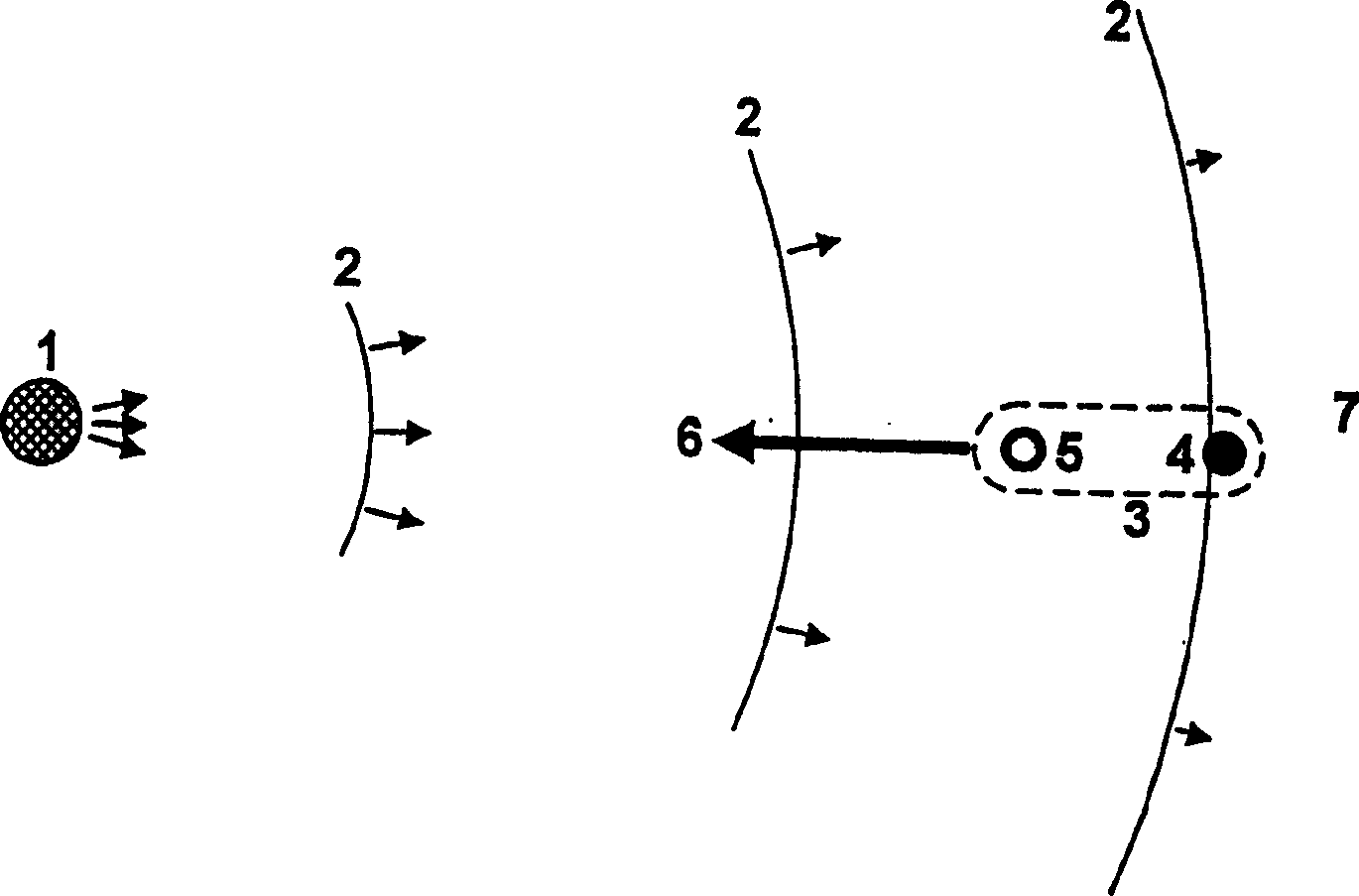
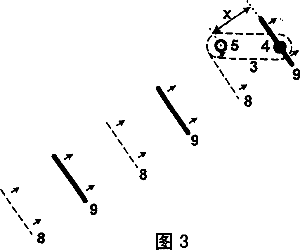
[0084] Figures 1 to 4 The impingement of sound waves on a microphone is shown according to one embodiment of the invention.

[0085] The microphone is represented by an array microphone array 3 comprising a plurality of microphone elements. In this embodiment, two microphone units 4 and 5 are provided.

[0086] The microphone unit may be any suitable transducer form for converting sound waves into electrical audio signals, such as an electrostatic vibrating plate or a moving coil-type device.

[0087] exist figure 1 In , the sound wave 2 originating from the sound source 1 is received by the array microphone array 3 . The array 3 is arranged (ie, a straight line connecting the microphone elements 4 and 5 ) such that the axis of the microphone-array 3 is parallel to the propagation direction of the sound wave 2 . In other words, the microphone is directed directly at the sound source 1, as indicated by arrow 6 which indicates the dir...


PUM


Abstract

A directional microphone is disclosed which comprises a microphone array (3) having a plurality of microphone elements (4,5,12,13) of which the element (4) is a rear element and the other elements are forward elements. A processor (19,31) is connected to the elements. The processor can be a hardware processor for processing signals or it can be a software controlled system for processing signals. The processor determines the arrival of a wave at one of the forward elements (5,12,13) and thereafter establishes a window of opportunity for receipt of the wave at the rear element (4). The window of opportunity is set such that only waves emanating from a particular direction will arrive in that time frame, thereby enabling acoustic waves from that direction to the processed by the microphone and other waves from different directions eliminated. The angle of arc of the microphone from which acoustic waves are received and processed can be set by changing the size of the window of opportunity t3-t2. In the hardware implementation, the processor includes filters (21,22), zero cross-over detectors (23,24), monostables (25,26) and flip-flop (28) for setting a timing signal and triggering the flip-flop (28) to control the switch (29) so that if a wave does arrive at the element (4) within the bandwidth of the filters (21,22), an audio signal corresponding to the wave is transmitted from the element (4) through the switch (29) to an output (30).

Description

field of invention [0001] The invention relates to a directional microphone. Background technique [0002] Current microphone technology has many limitations. [0003] Microphones are the weakest link in a hi-fi system, as they are believed to add the most distortion to the recorded or amplified signal. Both film sets and film productions were limited by the use of microphones. Usually, the microphone needs to be placed close to the target to reduce the pickup of unwanted sounds from the surrounding environment. This will really interfere with the shoot. [0004] Placement distance can also be an issue in quiet environments, for example, where the effective pickup range is limited. [0005] Outdoor broadcasts, such as live interviews, are often subject to the above limitations plus suffer from very high levels and interference from various sources of unwanted sound that may be picked up by the microphone and thus transmitted along with the desired sound signal that the m...

Claims


Application Information

Patent Timeline
IPC IPC(8): H04R3/00H04R25/00H04R1/40
CPCH04R25/407H04R3/005
Inventor 伊恩·罗伯特·西蒙斯伊恩·威廉姆·泰吉
Owner 约翰·安东尼·霍利
Learn More