Ink jet printing head
An inkjet print head and nozzle technology, applied in printing and other directions, can solve the problems of not allowing the formation of a buffer cavity and reducing the rigidity of the print head.
- Summary
- Abstract
- Description
- Claims
- Application Information
AI Technical Summary
Problems solved by technology
Method used
Image
Examples
Embodiment Construction
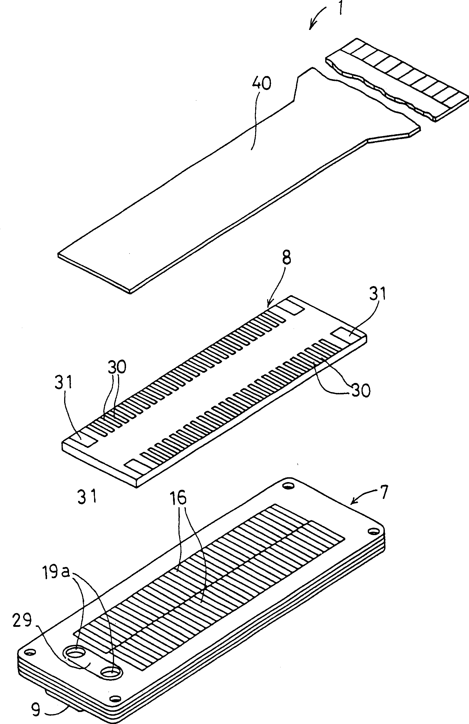
[0017] will refer to Figures 1 to 4 An inkjet printhead 1 according to an embodiment of the present invention is explained. In this inkjet print head 1, a flexible flat cable 40 is bonded to the upper surface of a sheet-shaped piezoelectric actuator 8 to be connected with an external device, and the piezoelectric actuator 8 is bonded to a cavity unit 7 . Ink is ejected from nozzles opening on the lower surface of the chamber unit 7 .
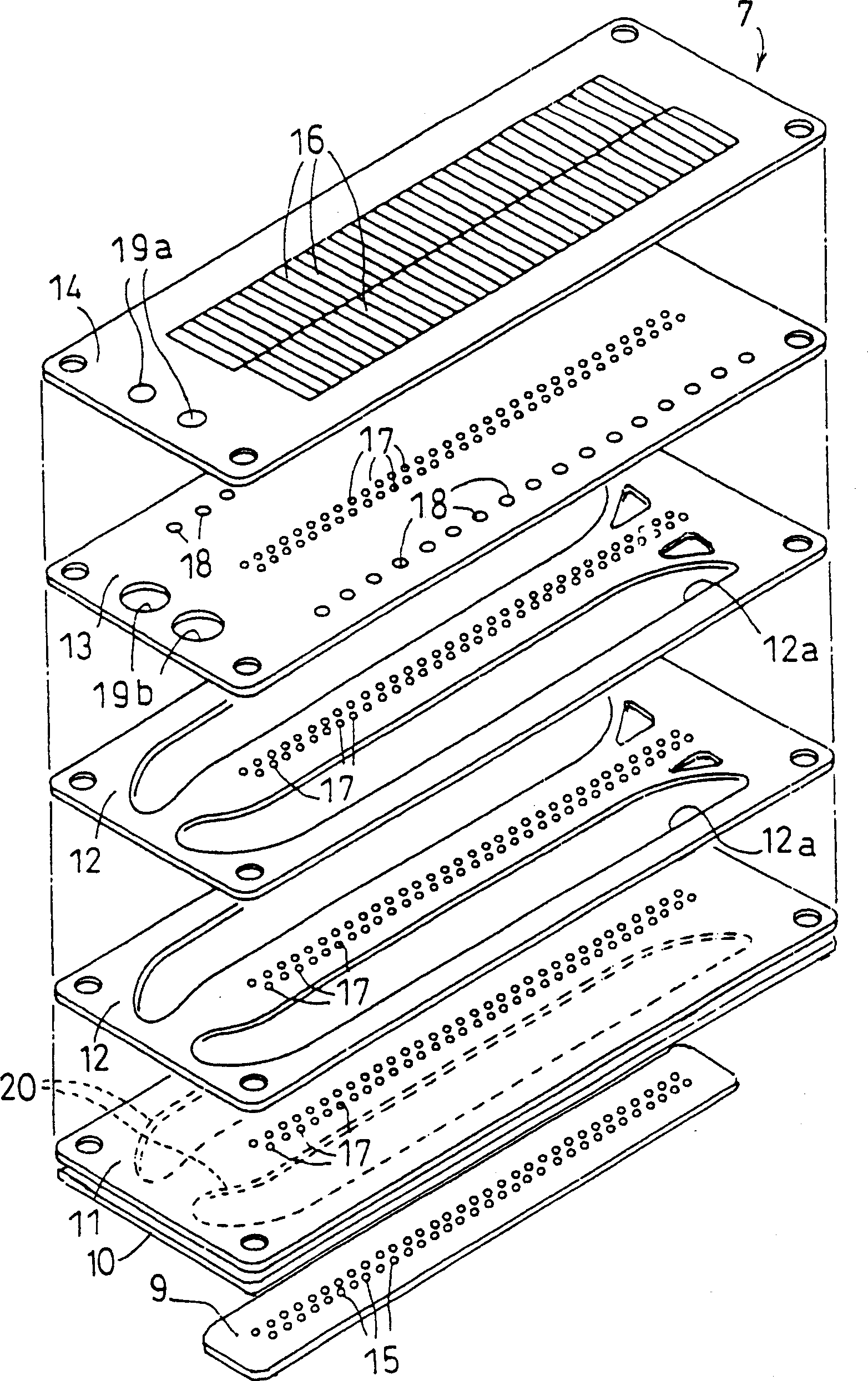
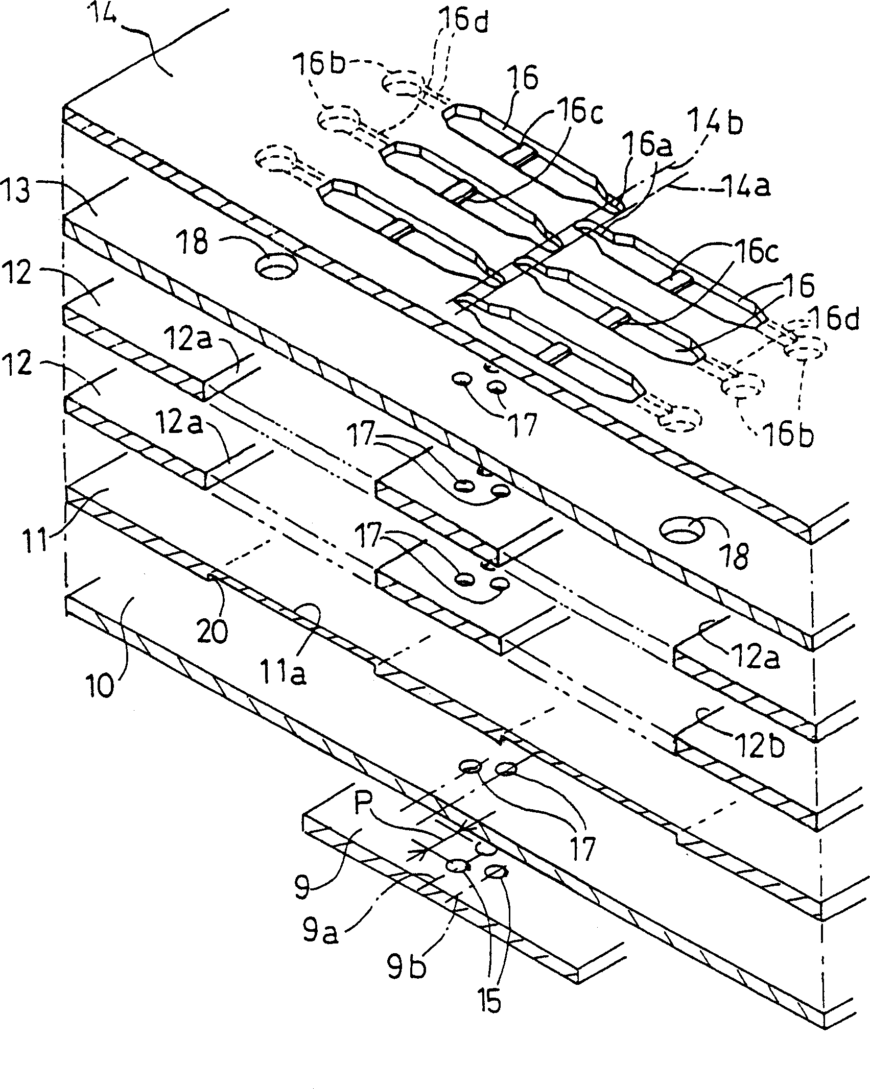
[0018] will refer to figure 2 and image 3 The structure of the chamber unit 7 will be described. The cavity unit 7 is formed by laminating and bonding seven layers of sheets, namely a nozzle plate 9, a cover plate 10, a buffer plate 11, two manifold plates 12, 12, a partition plate 13, and a base plate 14. form. In this embodiment, each layer of plates 10, 11, 12, 12, 13, 14, except the nozzle plate 9, is made of 42% nickel steel and has a thickness of about 50-150 microns. Openings and grooves are formed in these plates as ink channel...
PUM
 Abstract
Description
Claims
Application Information
 - R&D
- Intellectual Property
- Life Sciences
- Materials
- Tech Scout
- Unparalleled Data Quality
- Higher Quality Content
- 60% Fewer Hallucinations
Browse by: Latest US Patents, China's latest patents, Technical Efficacy Thesaurus, Application Domain, Technology Topic, Popular Technical Reports.
© 2025 PatSnap. All rights reserved.Legal|Privacy policy|Modern Slavery Act Transparency Statement|Sitemap|About US| Contact US: help@patsnap.com


