
Interlocking revetment block with array of vegetation holes

Active Publication Date: 2012-02-28
EROSION PREVENTION PRODS
View PDF18 Cites 17 Cited by
  • Summary
  • Abstract
  • Description
  • Claims
  • Application Information

AI Technical Summary

Benefits of technology

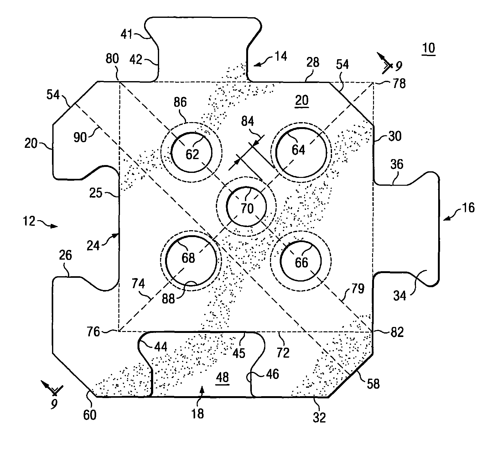
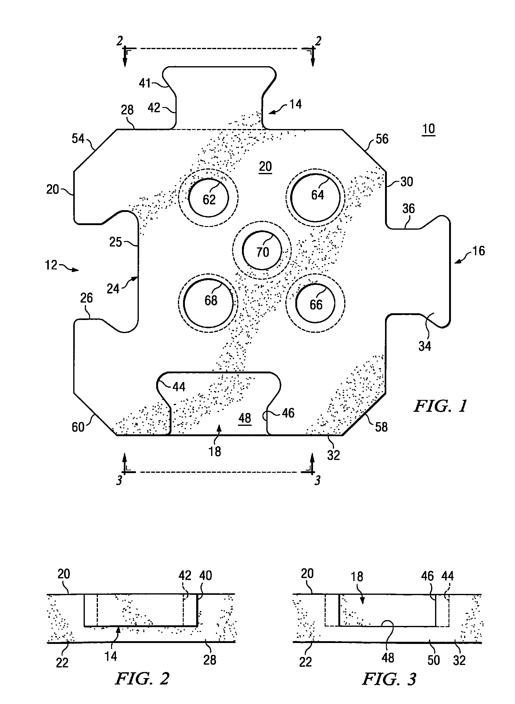
[0010]Disclosed is an erosion control block that provides interlocking capabilities with neighbor blocks of a mat. According to a feature of the invention, plural holes are formed through the block, from the top surface to the bottom surface to provide vegetation growth, as well as relief of hydrostatic pressure. The holes are constructed with diameters related to the thickness of the block to maximize the hydraulic stability thereof.
[0011]According to another feature of the invention, the holes are located in the block to also allow a workman to grasp the block using the holes to lift the same. However, the placement of the holes does not compromise the structural integrity of the block.
[0013]Another advantage of the use of multiple holes, is that each hole is tapered to flare out at the bottom of the block to enlarge the open area to the ground to allow a greater degree of vegetation to grow through the block. The tapered holes also facilitate the grasping of the block by a workman.

Problems solved by technology

It is also difficult to make a concrete slab that is adapted to slow down the velocity of water that flows thereover.
Otherwise, the hydraulic lift of the flowing water can cause the blocks to actually lift off the ground and be carried or otherwise moved so that the erosion protection is compromised.
This solution is costly and often prevents the installation of the heavy blocks by persons who must lift each block and place it into position with others to form the mat.
While the vegetation holes in erosion control blocks allows anchoring thereof by vegetation, such holes can also present a disadvantage.
The resulting water turbulence and the hydraulic forces can impart a force on the block that tends to lift the upstream portion of the block.
If this occurs, then the surrounding blocks are more easily dislodged from the mat, whereupon the integrity of the entire mat of blocks can be compromised.
Such overkill renders the blocks unnecessarily large, heavy and difficult to install.

Method used


Image

  • Interlocking revetment block with array of vegetation holes
  • Interlocking revetment block with array of vegetation holes
  • Interlocking revetment block with array of vegetation holes

Examples


Embodiment Construction

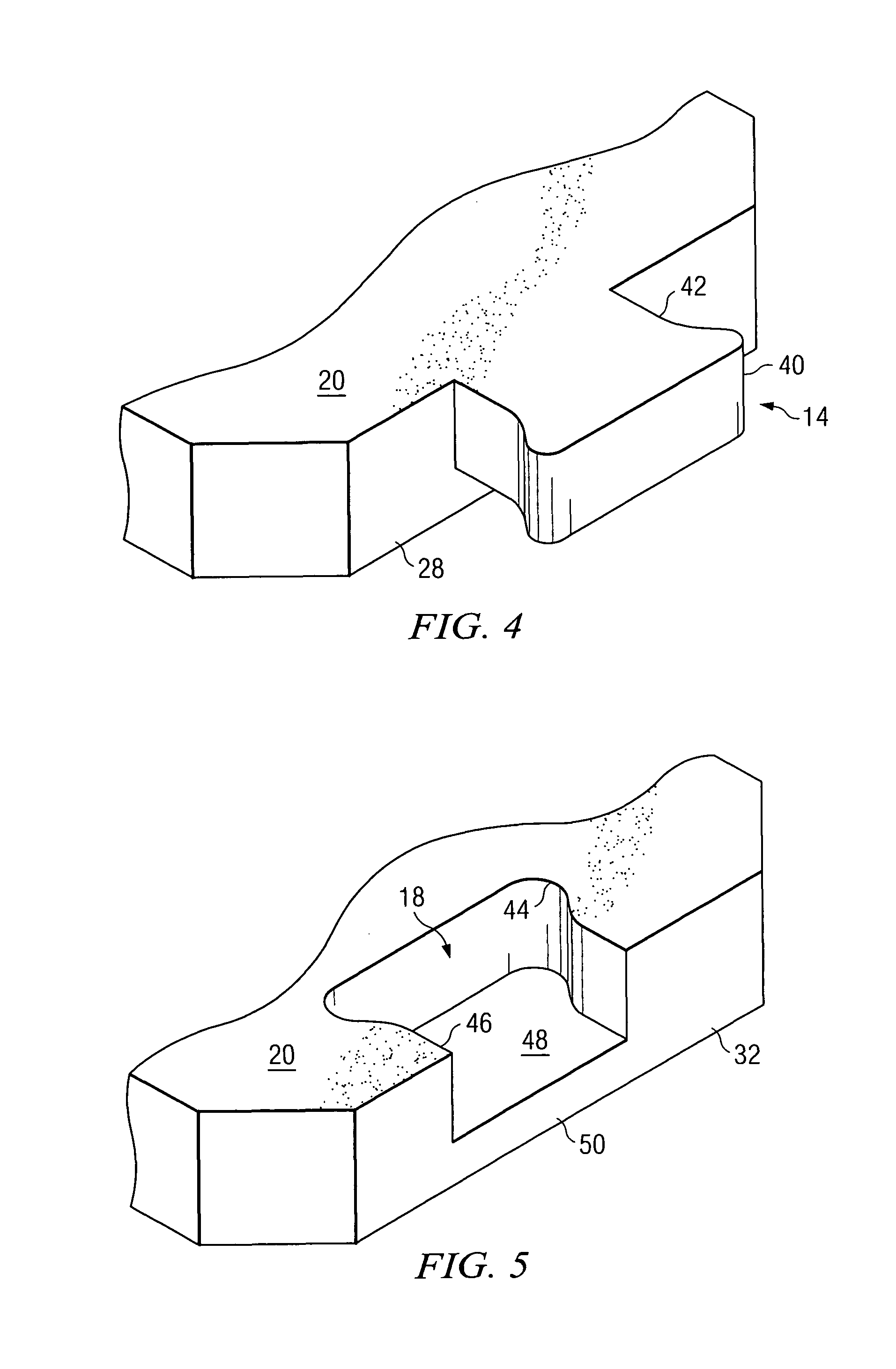
[0026]An erosion control block 10 constructed according to the invention is shown in FIG. 1. The block 10 includes a full depth socket 12, a partial thickness arm 14, a full thickness arm 16 and a partial depth socket 18. The full depth socket 12 is formed axially into a side edge 20 of the block 10, and extends from a top surface 20 of the block 10 to a bottom surface 22, shown in FIG. 6. The full depth socket 12 includes an enlarged cavity 24 connected to the edge 20 of the block 10 by a narrowed inlet 26. The full depth socket 12 includes an inner edge 25. The full depth socket 12 is the same general shape as the full thickness arm 16, but somewhat larger in size so that a full thickness arm of a similarly-constructed neighbor block can be fitted into the full depth socket 12 of the block 10. The arms 14 and 16 are formed orthogonal to each other on respective adjacent side edges 28 and 30 of the block 10. Similarly, the sockets 12 and 18 are formed orthogonal to each other into ...


PUM


Abstract

A concrete revetment block having interlocking arms and sockets and an array of vegetation holes. Two arms and two sockets are formed in the block to provide interlocking capabilities with neighbor blocks of a mat. One arm of the block is constructed with a partial thickness and one socket is constructed with a partial depth, thereby providing vertical interlocking capabilities with the neighbor blocks. An array of holes is formed through the block to allow vegetation to grow therethrough. Various holes are located in the block to allow easy grasping of the block by a workman for lifting the same. The holes are formed in the core square of the block, with respective diameters related to the thickness of the block to maximize the hydraulic stability of the block.

Description

TECHNICAL FIELD OF THE INVENTION[0001]The present invention relates in general to erosion control blocks, and more particularly to erosion control blocks with holes therein adapted for anchoring by vegetation growth therethrough.BACKGROUND OF THE INVENTION[0002]The erosion of soil on the earth continues to occur as rain and flood waters run from high elevations to lower elevations. Many efforts have been made to reduce the erosion of soil by interrupting the runoff of water, or at least slow down the water flow and thereby reduce the extent of erosion. Erosion control blocks are available for covering watershed areas to protect the underlying soil from being carried with the runoff water. Many styles, shapes and sizes of erosion control blocks are available for placement together to form a mat that covers the ground to be protected from erosion. The use of erosion control blocks is preferred over the use of a slab of concrete, as concrete can crack and settle if the underlying groun...

Claims


Application Information

Patent Timeline
IPC IPC(8): E02B3/12
CPCE02B3/123E02B3/14
Inventor DESHAW, JAMES R.SMITH, LEE A.
Owner EROSION PREVENTION PRODS
Learn More