

Liquid crystal display
A liquid crystal display device, liquid crystal technology, applied in the direction of static indicators, nonlinear optics, instruments, etc., can solve the problems of not obtaining, improving the aperture ratio, etc., and achieve the effect of improving orientation stability and optical characteristics
- Summary
- Abstract
- Description
- Claims
- Application Information
AI Technical Summary
Problems solved by technology
Method used
Image

Examples
Embodiment 1
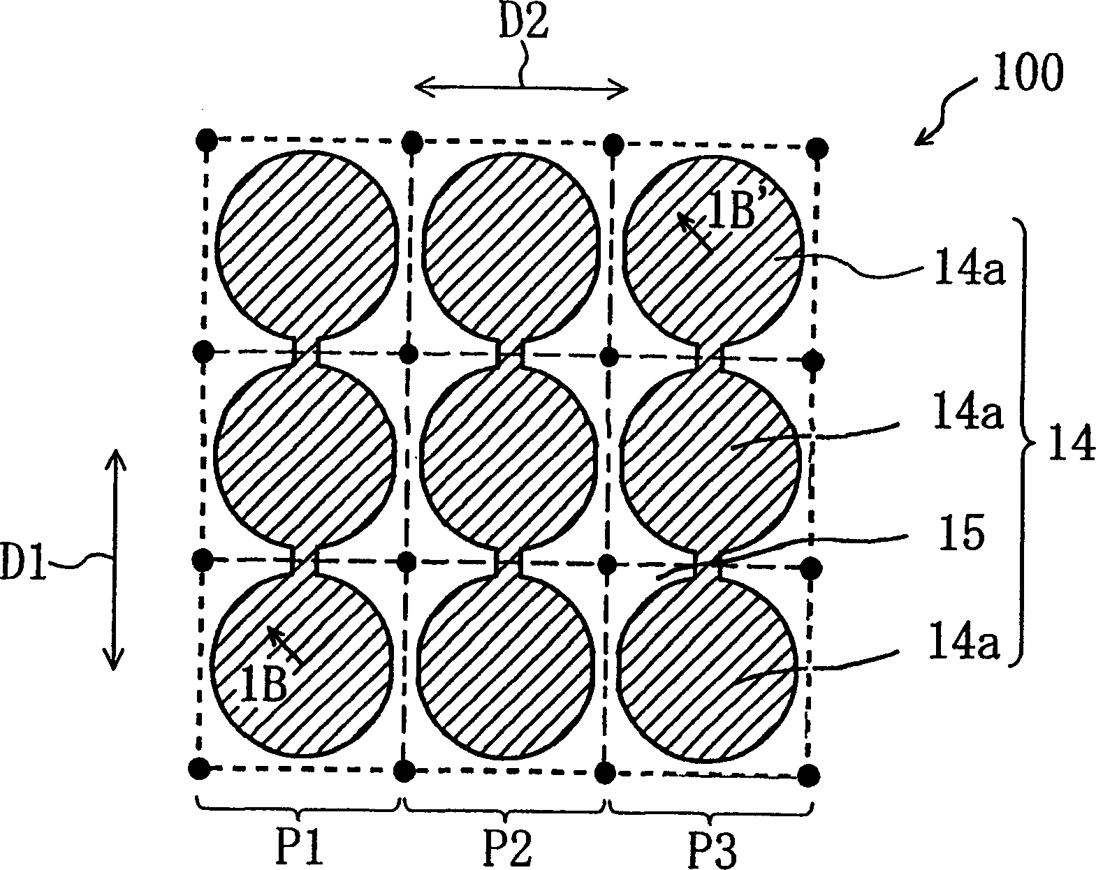
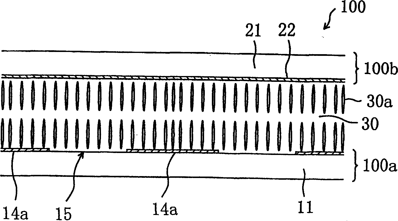
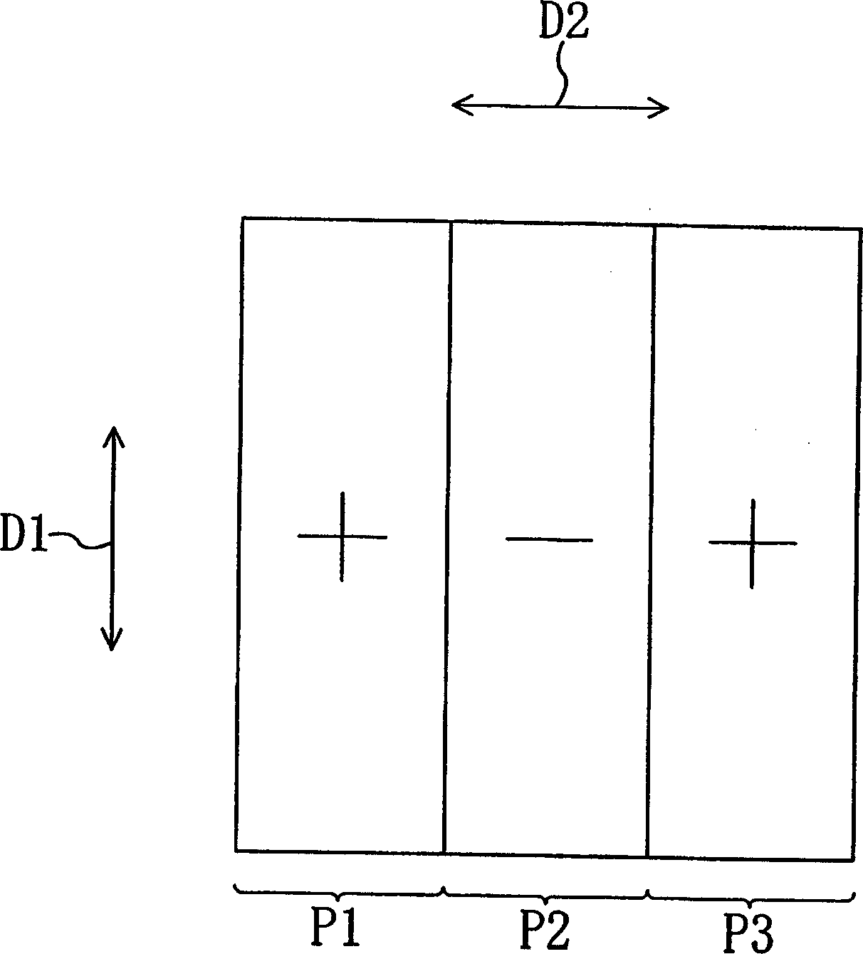
[0094] First, the electrode structure of the liquid crystal display device of the present invention and its function are described. The liquid crystal display device of the present invention has ideal display characteristics, and thus can be suitably used as an active matrix type liquid crystal display device. Embodiments of the present invention concerning an active matrix type liquid crystal display device using thin film transistors (TFTs) will now be described. However, the present invention is not limited thereto, and can also be used with an active matrix type liquid crystal display device having a MIM structure. In addition, while the embodiments of the present invention are described in terms of a transmissive liquid crystal display device, the present invention is not limited thereto, and may be additionally used with a reflective liquid crystal display device, and may even be additionally used with a transmissive-reflective liquid crystal display device described lat...
Embodiment 2
[0171] now refer to Figure 16A with Figure 16B The structure of one picture element region of the liquid crystal display device 200 according to Embodiment 2 of the present invention will be described. Also, in the following drawings, each element having substantially the same function as the corresponding element in the liquid crystal display device 100 will be denoted by the same reference numeral and will not be further described hereinafter. Figure 16A is a plan view viewed from the substrate normal direction, Figure 16B along Figure 16A Cross-sectional view taken along line 16B-16B'. Figure 16B A state where no voltage is applied across the liquid crystal layer is shown.
[0172] Such as Figure 16A with Figure 16B As shown in the liquid crystal display device 200 with Figure 1A with Figure 1B The liquid crystal display device 100 in the illustrated embodiment 1 is different in that the TFT substrate 200 a includes the protrusion 40 in the opening area 15 ...
Embodiment 3
[0198] According to the liquid crystal display device of embodiment 3 of the present invention and Figure 1A with Figure 1B The liquid crystal display device 100 in the illustrated embodiment 1 is different in that the counter substrate includes an alignment adjustment structure.
[0199] Figure 22A to Figure 22E A reverse substrate 300b with orientation adjusting structures 28 is schematically shown. Each element having substantially the same function as the elements of the liquid crystal display device described above will be denoted by the same reference numeral and will not be further described.
[0200] Figure 22A to Figure 22E The function of the alignment adjustment structure 28 shown is to align the liquid crystal molecules 30a of the liquid crystal layer 30 into a radial oblique alignment. It should be noted that, Figure 22A to Figure 22D The orientation adjustment structure shown in 28 and Figure 22E The alignment adjustment structure shown in is different...
PUM
 Abstract
Description
Claims
Application Information