Plate heat exchanger

A plate heat exchanger, along the plate technology, applied in the direction of indirect heat exchanger, heat exchanger type, heat transfer modification, etc., can solve the problem that it is difficult to fully ensure pressure sealing, etc., to achieve good heat exchange performance, plate heat exchanger Effect of compact heater and improved pressure tightness

Inactive Publication Date: 2004-03-03
HITACHI JOHNSON CONTROLS AIR CONDITIONING INC
View PDF1 Cites 8 Cited by
  • Summary
  • Abstract
  • Description
  • Claims
  • Application Information

AI Technical Summary

Problems solved by technology

[0003] The above-mentioned conventional technology is designed for a vapor compression type refrigeration cycle, and therefore, it is difficult to sufficiently ensure pressure-tightness when using a high-pressure refrigerant typified by R410A and carbon dioxide
Also, when it is used as an evaporator such as a chiller unit, there is a fear that the cold water freezes and the seal breaks when the operating temperature on the refrigeration cycle side drops significantly, thereby mixing the water and the refrigerant

Method used


Image

  • Plate heat exchanger
  • Plate heat exchanger
  • Plate heat exchanger

Examples


Embodiment Construction

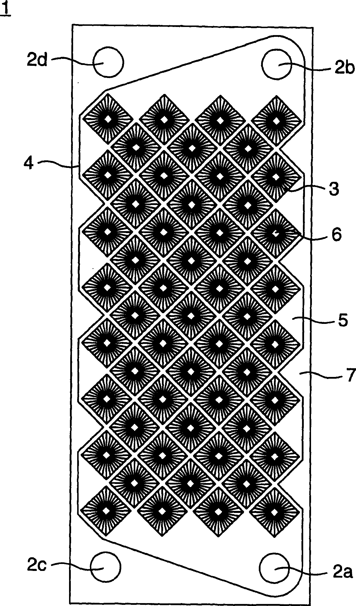
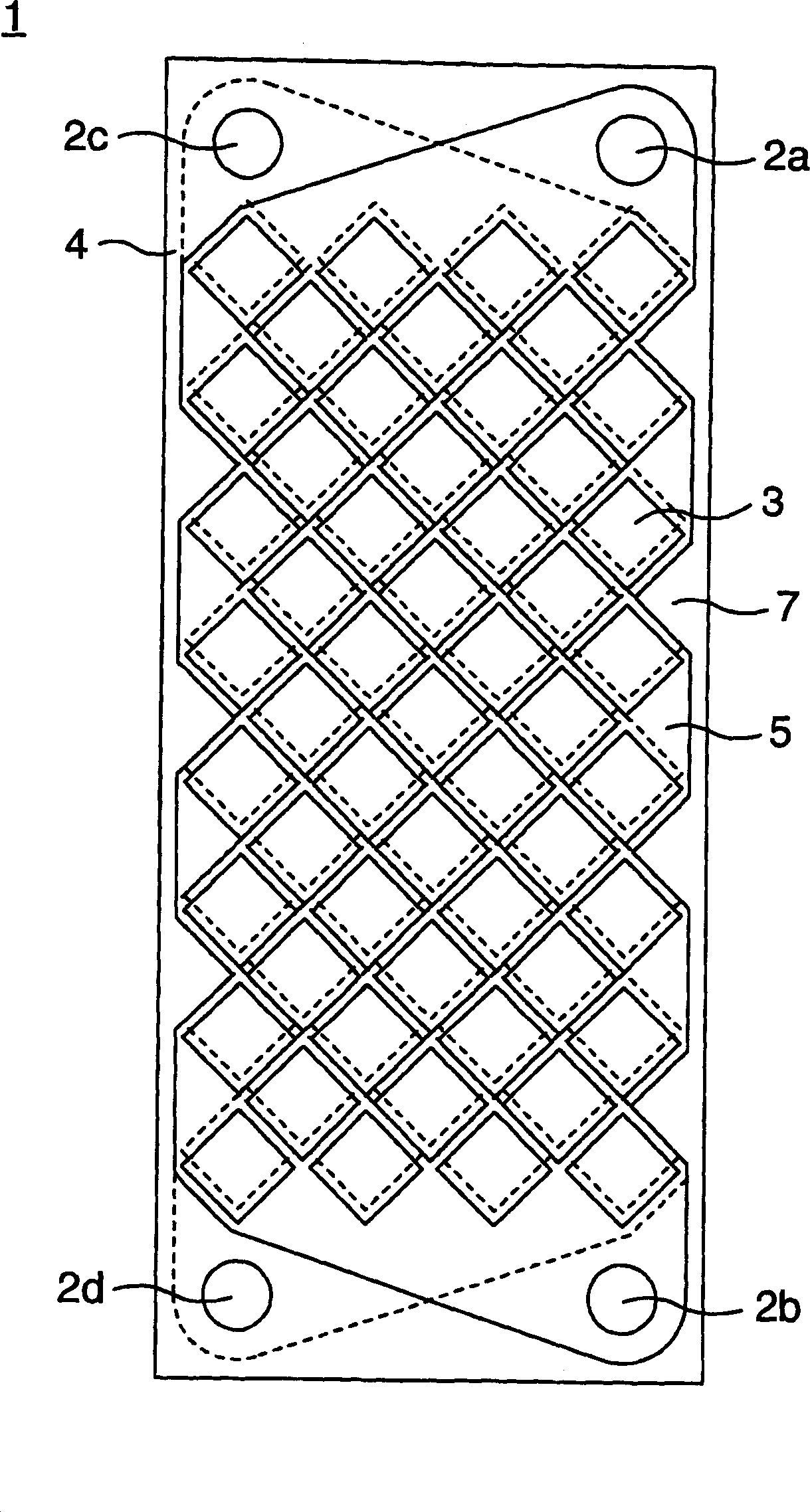
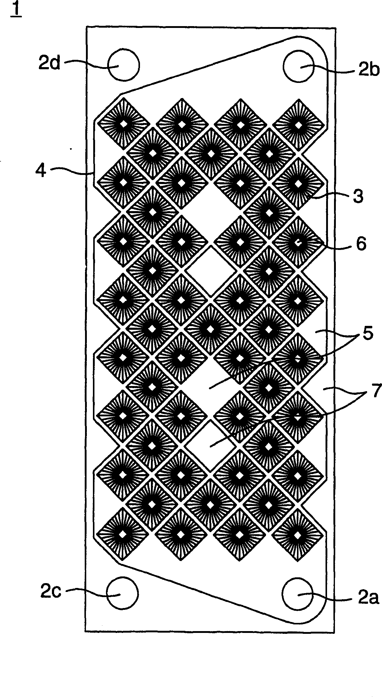
[0019] The following will refer to Figures 1 to 3 Embodiments of the present invention are described. figure 1 is a plan view showing the plate 1 constituting the plate heat exchanger, and figure 2 Yes (when from figure 1 When viewed from the back side) is a plan view showing a state when the boards 1 are turned upside down alternately so as to be stacked on top of each other.

[0020] The plate 1 is formed by press working of a thin metal plate and has four openings 2a to 2d. Only two openings 2 a , 2 b define one flow channel in the plate 1 , and this flow channel is separated by the sealing portion 4 . Pyramidal heat transfer surface elements 3 are formed on the plate 1, the heat transfer surface elements 3 define peaks or valleys along the thickness direction of the plate, and the upper end portion 6 of the heat transfer surface elements has a flat top, that is, the surface The element 3 is in the shape of a truncated quadrangular pyramid. The pyramidal heat transfe...


PUM


Abstract

A plate type heat exchanger comprises a plurality of plates (1) stacked on one another. Each of the plates (1) has a seal portion (4), which is provided on an outer peripheral portion of the plate (1) and with an interior of which inflow and outflow ports (2a,2b,2c,2d) of heat exchanging fluids are communicated, and heat-transfer surface elements (3) formed in a mountain-shaped manner in a thicknesswise direction of the plate (1) and arranged to form flow passages within the seal portion (4). The heat-transfer surface elements (3) are in the form of a quadrangular pyramid having flat top (6). The seal portion (4) has flat portions (5) on outer peripheral portions of the flow passages to define a bottom surface, and mountain portions (7), which extend upright from the flat portions and of which tops are formed to be flat in shape.

Description

technical field [0001] The invention relates to a plate heat exchanger, in particular to a heat exchanger for refrigeration and air conditioning, which is suitable for vapor compression refrigeration cycle. Background technique [0002] Generally, in order to make a plate heat exchanger compact and improve its heat transfer performance, it is known to form a heat transfer surface element having peaks and valleys along the plate thickness direction, and to form minute ribs on the surface of the element, which The structure is described in International Application WO00 / 16029. [0003] The above-mentioned conventional technology is designed for a vapor compression type refrigeration cycle, and therefore, it is difficult to sufficiently ensure pressure-tightness when using a high-pressure refrigerant typified by R410A and carbon dioxide. Also, when it is used as an evaporator such as a cooler unit, there is a fear that the cold water freezes and the seal breaks when the operat...

Claims


Application Information

Patent Timeline
Patent Type & Authority Applications(China)
IPC IPC(8): F25B1/00F25B39/00F28D9/00F28F3/04F28F3/08F28F3/10F28F13/18
CPCF28F3/083F28D9/005F28F13/185F28F3/044
Inventor 松島均
Owner HITACHI JOHNSON CONTROLS AIR CONDITIONING INC
Why Eureka
Try Eureka