
Moulding apparatus with external mold block cooling

A technology of model blocks and equipment, applied to corrugated products, household appliances, and other household appliances, etc., can solve the problems that the cooling air cannot keep in contact with the model blocks, etc.

Inactive Publication Date: 2004-03-17
曼夫瑞德·A·A·鲁波克 +1
View PDF0 Cites 0 Cited by
  • Summary
  • Abstract
  • Description
  • Claims
  • Application Information

AI Technical Summary

Problems solved by technology

However, in accordance with traditional practice, this does not ensure that the cooling air remains in contact with the model block, the cooling air just flows freely outward from the model block rather than being contained on the surface of the model block

Method used


Image

  • Moulding apparatus with external mold block cooling
  • Moulding apparatus with external mold block cooling
  • Moulding apparatus with external mold block cooling

Examples


Embodiment Construction

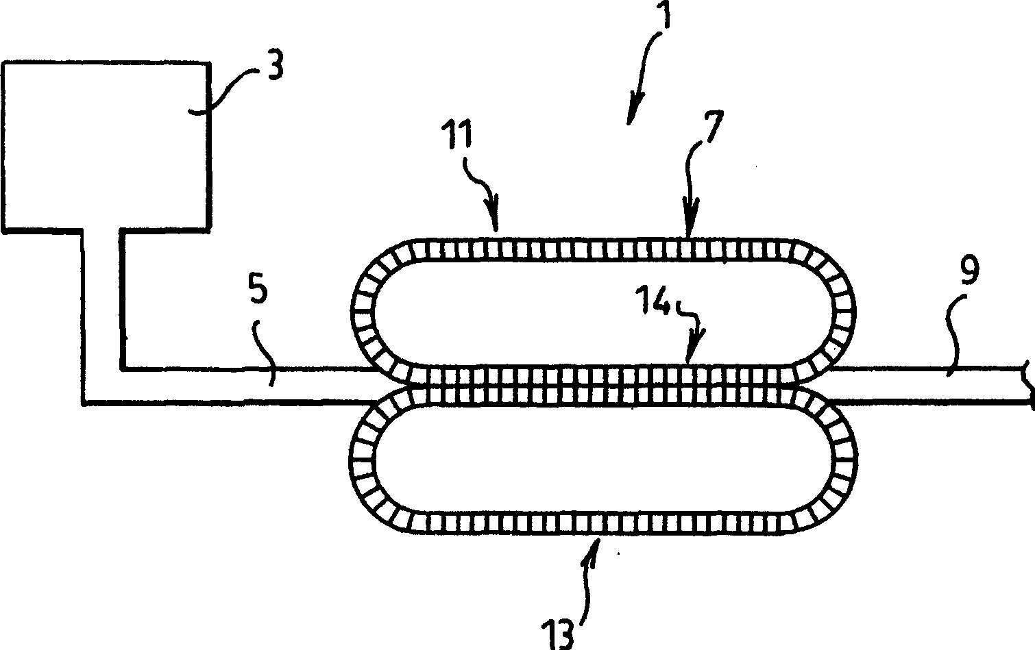
[0016] figure 1 The pipe molding apparatus 1 shown comprises an extruder 3 which sends molten plastic through a die 5 to a plastic corrugator 7 . The plastic corrugator 7 includes an upper annular formation 11 and a lower annular formation 13 of model block segments which are brought together to form a mold tunnel which accepts molten plastic to form a plastic tube 9. The plastic pipe is discharged from the downstream end of the mold channel.

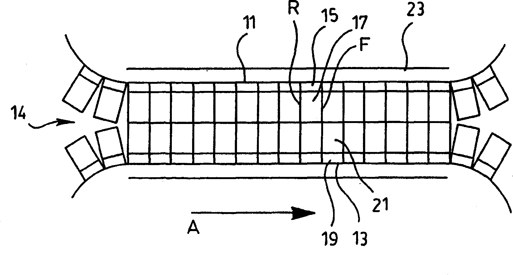
[0017] figure 2 Model block segments 17 are shown loaded by model block segment conveyor chain 15 into the upper queue 11 of the corrugator and model block segments 21 are loaded by conveyor chain 19 into the lower queue 13 of the corrugator. These upper and lower rows of model block segments all move in the direction of arrow A through the model tunnel 14 . Each model block segment such as figure 2 Reference numeral 17 is shown having a front F and a rear R facing the direction of movement of the model block through the model tun...


PUM


Abstract

A mold block for use with other mold blocks in forming a moving mold tunnel of a plastic molding apparatus has front and rear surfaces which face in direction of travel of the mold block and opposite side surfaces between the front and rear surfaces. Each of the side surfaces of the mold block includes a closed sided open ended channel which extends across the side surface to form a passage to receive a cooling medium to be fed into the passage for cooling of the mold block.

Description

technical field [0001] This invention relates to the cooling of mold blocks for movable mold channels in plastic molding equipment. Background technique [0002] Of extreme importance in plastic molding equipment is the cooling of the mold blocks in the active mold tunnel while the mold blocks are in the product forming stage. Cooling of the mold block can bring significant benefits to the product itself. [0003] An example of an active model channel used in molding equipment is a plastic pipe model. Existing plastic pipe models are known to operate with internal cooling of the mold blocks as they move through the mold tunnels. In some instances, this internal cooling is accomplished with cooling water, but it can be difficult to control the flow of water and prevent it from dripping from the molding equipment. [0004] Cooling gas is also used for internal cooling of the model block. Such model blocks must undergo special in-house machining. This is costly and extreme...

Claims


Application Information

Patent Timeline
Patent Type & Authority Applications(China)
IPC IPC(8): B29C33/02B29C33/04B29C33/36B29C35/16B29C48/09B29C48/13B29C48/30B29C48/355B29C49/00
CPCB29C2791/006B29C49/0021B29C47/126B29L2016/00B29C49/4823B29C2035/1658B29C35/16B29C2791/007B29C47/0033B29L2023/18B29C33/36B29C33/04B29C48/13B29C48/303B29C48/09
Inventor 曼夫瑞德·A·A·鲁波克斯蒂芬·A·鲁波克
Owner 曼夫瑞德·A·A·鲁波克
Learn More