
Micro-plastic molding method and apparatus for micro-device

A micro-plastic and micro-device technology, applied in forming tools, metal extrusion control equipment, metal extrusion and other directions, can solve the problems of forming materials and forming process limitations, large deformation resistance of micro-cold forming, uneven material flow, etc. , to achieve the effect of easy automatic production, uniform micro-forming process and easy focusing

Inactive Publication Date: 2008-02-27
JIANGSU UNIV
View PDF5 Cites 30 Cited by
  • Summary
  • Abstract
  • Description
  • Claims
  • Application Information

AI Technical Summary

Problems solved by technology

[0006] 1. The forming materials and forming process are limited, especially the forming of micro devices of difficult-to-form materials cannot be completed under slightly cold forming conditions
[0007] 2. Due to the large deformation resistance of micro-cold forming, and it is greatly affected by the type of material, grain size and orientation, resulting in micro-forming deformation, uneven material flow, and unstable process parameters
[0008] 3. Most of the heating in the microplastic forming system adopts indirect (embedding thermocouples in the mold) or contact heating (oil bath, heating furnace, or friction heating), the process is complicated and the temperature is not easy to control. And the scope of application is relatively narrow, mainly used in the heating of micro-forming of superplastic materials
However, for the microplastic forming process, there is no method and device for auxiliary heating of the workpiece material by laser to reach the temperature of micro-temperature forming or micro-thermoforming.

Method used


Image

  • Micro-plastic molding method and apparatus for micro-device
  • Micro-plastic molding method and apparatus for micro-device

Examples


Embodiment Construction

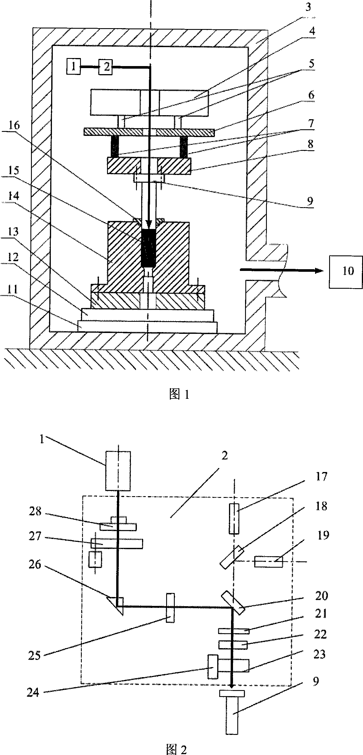
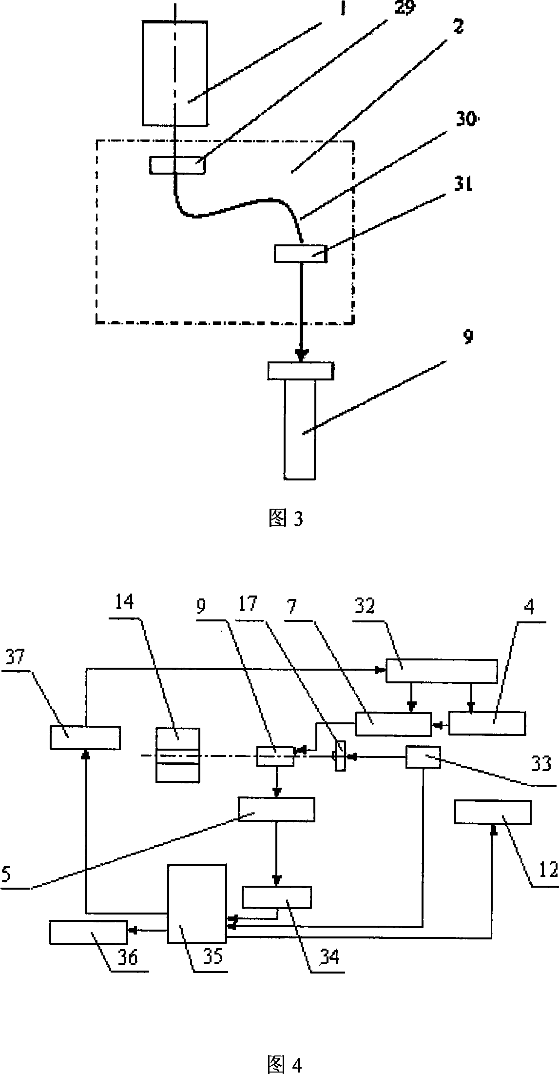
[0036] The details and working conditions of the specific device proposed by the present invention will be described in detail below in conjunction with FIG. 1 , FIG. 2 , FIG. 3 and FIG. 4 .

[0037] The microplastic forming system of the whole micro device consists of five parts: laser heating system, micro forming system, loading system, control system and installation platform. The laser heating system consists of a laser 1 connected to an optical path system 2. The optical path system 2 consists of a laser 1, a beam expander 28, a laser safety shutter 27 with safety measures, a prism 26, a collimator 25, a half-transparent mirror 20, Optical filter 21, aperture 22, short-focus objective lens 23 for adjusting spot size, five-position adjustment frame 24 for adjusting objective lens, and observation subsystem composed of CCD17, half-transparent mirror 18 and white light source 19. The laser heating system may also consist of a laser 1 , an acousto-optic modulator 29 , a sing...


PUM


Abstract

The invention discloses a microplastic shaping method and device of microelement in the microplastic piece preparing and shaping technical domain, which comprises the following parts: laser heating system, microshaping system, loading system, control system and assembling platform, wherein the flat-top laser beam emitted by laser is loaded on the surface of microelement surface through transmittable terrace die, which utilizes laser to do non-contact heating of working piece and heat conductivity; the heat work piece material is below recrystallizing temperature for shaping temperature scale; the terrace die does feeding movement towards female die through microdriving system; the loading system combines the microdriving system to realize loading action for microblank to finish microplastic shaping. The invention reduces the deformation resistance of material at non-contact heating on the upper surface of working piece through laser, which increases the evenness of material fluidity for batching manufacturing of microelement to realize automation manufacturing easily.

Description

technical field [0001] The invention relates to the technical field of micro-device manufacturing and micro-plastic forming, in particular to a micro-plastic forming method and device for micro-device, which is suitable for micro-plastic forming of micro-metal devices, especially suitable for conventional micro-forming methods that are difficult or impossible to form The micro-forming of materials can realize the low-cost mass production of micro-devices. Background technique [0002] Miniaturization is an important way to obtain competitive and multifunctional engineering systems, and product miniaturization has become an unstoppable trend in the industry. Micro-electro-mechanical systems (MEMS) characterized by small dimensions or operating scales have better performance and functions in terms of energy consumption, response time, precision, thermal deformation, vibration and speed, and are widely used in aerospace, precision instruments, and biomedicine. And national def...

Claims


Application Information

Patent Timeline
IPC IPC(8): B21C23/00B21C29/00B21C31/00B21C25/02B21C23/21B21D37/16B21J1/06
Inventor 王匀许桢英张凯孙日文蔡兰袁国定董培龙杨昆戴亚春姚红兵吕盾
Owner JIANGSU UNIV
Learn More