Switchboard

A switchboard and equipment installation technology, applied in substation/power distribution device casing, electrical components, substation/switch layout details, etc., can solve problems such as equipment skew, deterioration of completed state, and time-consuming

Inactive Publication Date: 2004-03-24
KAWAMURA ELECTRIC INC
View PDF0 Cites 2 Cited by
  • Summary
  • Abstract
  • Description
  • Claims
  • Application Information

AI Technical Summary

Problems solved by technology

[0003] However, in the prior art described above, when the equipment is not installed on the equipment installation rail as a gap at the beginning, and the equipment is installed later, it is necessary to process the wiring cover, so it takes a lot of time and effort.
In addition, due to post-processing, there is a possibility that the finished state may deteriorate
In addition, since the positioning of the part as the gap part is performed by using the fixture used in the past, there is a possibility that the equipment will be installed obliquely.

Method used


Image

  • Switchboard
  • Switchboard
  • Switchboard

Examples


Embodiment Construction

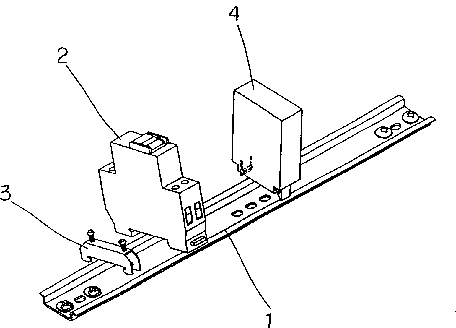
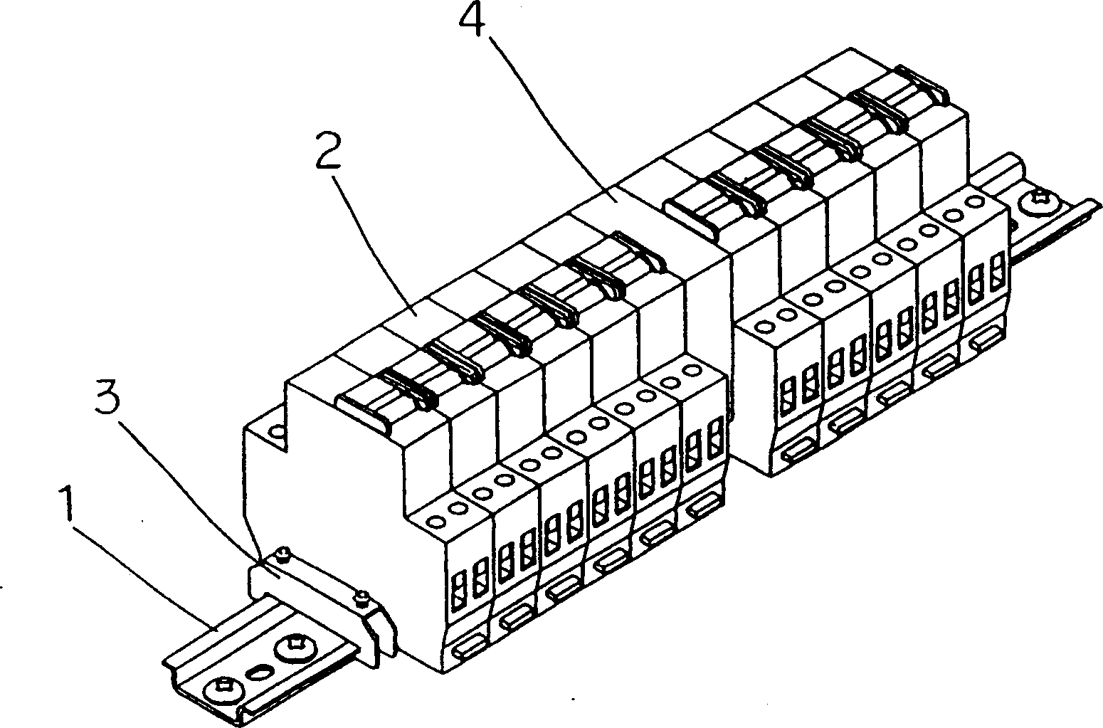
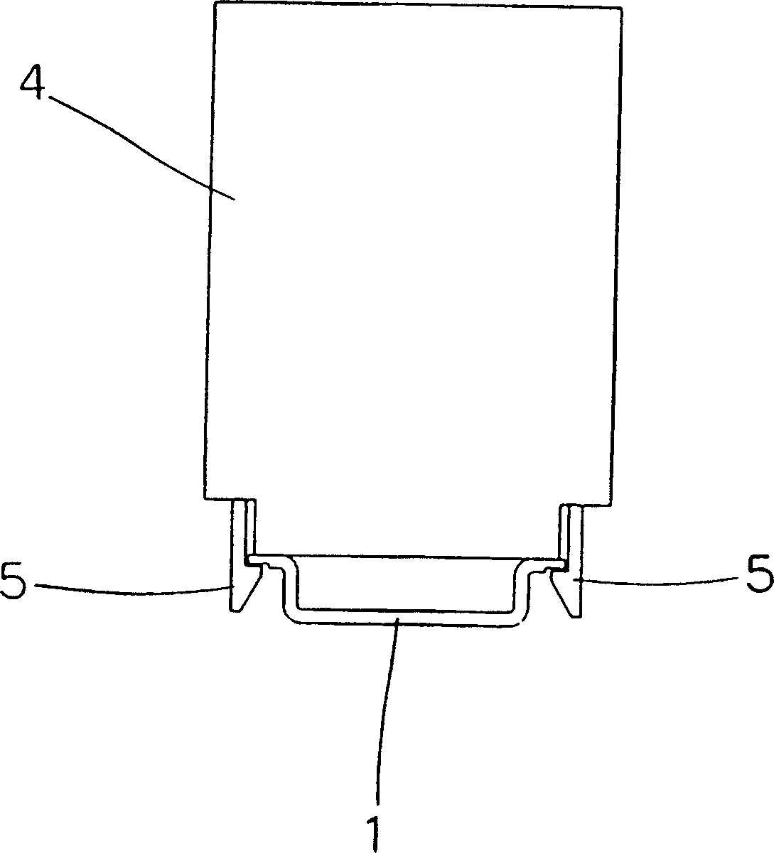
[0021] refer to Figure 1 to Figure 4 The accompanying drawings illustrate an embodiment of the switchboard of the present invention.

[0022] The configuration is such that the panel is installed on the switchboard, the equipment installation rail 1 is laid on the panel, and equipment such as the circuit breaker 2 is arranged on the equipment installation rail 1 . The equipment installation rail 1 is cut into the required length in advance, bolts are fastened on the panel, and the fixtures 3 for equipment positioning are installed on the left and right of the equipment installation rail 1 . Arrange the circuit breakers 2 between the fixing pieces 3 .

[0023] When there is a gap between the circuit breaker 2 and the circuit breaker 2, a spacer 4 formed in a shape similar to the circuit breaker 2 and having the same width as the circuit breaker 2 is installed on the equipment installation rail 1 to fill the gap. At the same time, the circuit breaker 2 is supported.

[0024]...


PUM


Abstract

Provided is a distribution board in which a space generated between arrayed breakers 2 is easily filled to surely secure a space. If an equipment space is generated on an equipment-fitting rail 1, the equipment-fitting rail 1 is fitted with a spacer 4, similarly to the equipment. A bottom surface is provided with a claw part, which can engage with the equipment-fitting rail, and a spacer for the equipment-fitting rail is used, and a space is secured by using simple operations.

Description

technical field [0001] The present invention relates to a switchboard in which a panel etc. are installed on a box body with an opening, and equipment such as a circuit breaker is mounted and fixed on an equipment installation rail already installed on the panel. Background technique [0002] Such as Figure 5 As shown, installation holes 22 are set on the equipment installation rails 21. In the past, in terms of fixing the equipment installation rails 21, the equipment installation rails 21 were cut to the required length in advance, and the bolts 23 were inserted through the installation holes 22 and Fixing hole, the equipment installation rail 21 is fastened on the panel etc. that offer the fixing hole (not shown) of its usefulness of installing equipment. Install a fixing piece 24 on any position of the fixed equipment installation rail 21, and use the fixing piece 24 to locate electrical equipment such as a circuit breaker 25. As shown in FIG. 6 , an opening 27 for exp...

Claims


Application Information

Patent Timeline
IPC IPC(8): H02B1/42H01H73/06H02B1/015H02B1/30
Inventor 梶间龙二
Owner KAWAMURA ELECTRIC INC
Why Eureka
Try Eureka